So, as mentioned in my last post this time I’ve put in the wire links and wraps needed to test the first bit of the arithmetic card. With these in place I can make sure everything works as it should before repeating it all eight times over to make the full 8-bit adder.
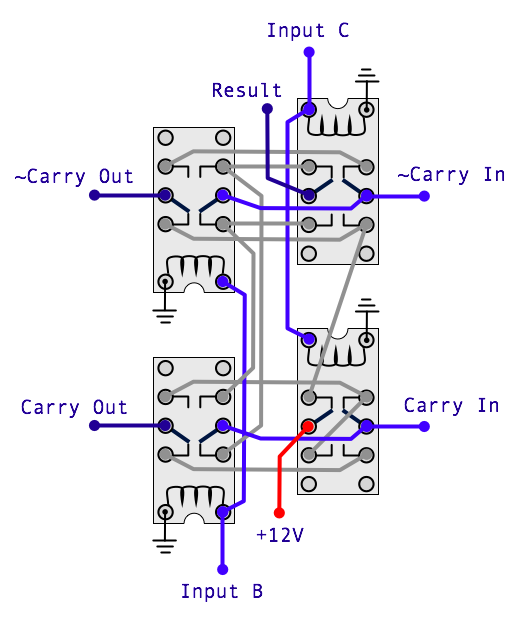
As a quick reminder here’s the diagram for the 1-bit full adder:
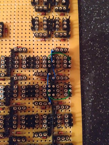
Reproducing this on the arithmetic card gives the following (on the front of the card):
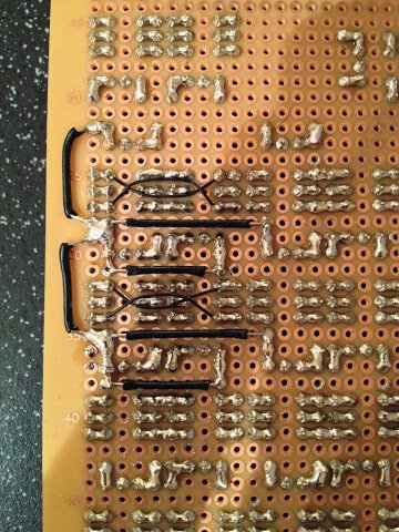
and the following (on the back of the card):
To be able to test the circuit above I needed to temporarily hook up the positive and ground power (through ‘cunning’ use of crocodile clips) and then link up the Carry In, Input B and Input C. First time around I forgot about connecting the inverse Carry In as well as the regular Carry In so was getting odd results but with everything finally hooked up correctly everything works as intended.
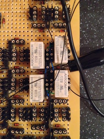
Here’s a picture of the circuit with relays inserted and inputs/power attached:
and another showing the whole arithmetic card along with the test board which supplies the inputs the circuit requires:
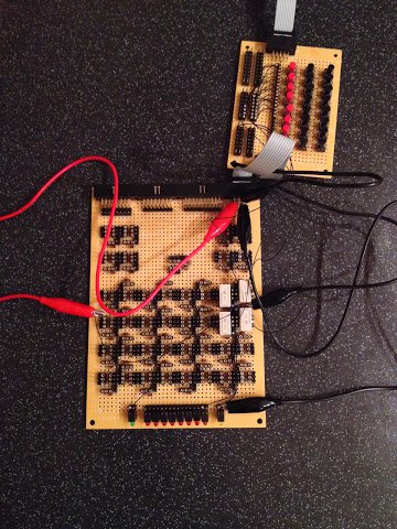
This time around the first four red buttons are hooked up to (from the left, in order): Input B, Input C, Carry In, ~Carry In. As usual, I’ve taken a quick video clip showing the circuit being tested:
Next job for this card will be to complete the remaining power rails underneath (another fiddly job) and then it’s on to the wire wrapping.