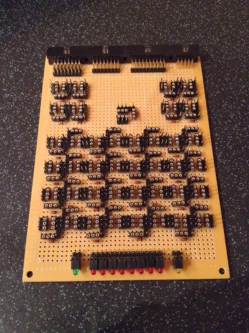
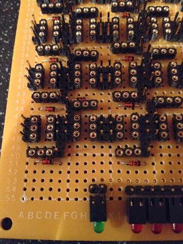
It’s always a fiddly job getting the relay sockets soldered in and the ALU arithmetic card proved no exception. With this in mind I’ve been spreading the work out over several mini sessions in accordance with my new post-Xmas lack of patience. Therefore it’s taken me a bit longer than it would otherwise to complete this stage of construction although to be fair I also got distracted with a Nixie clock kit my partner bought me for Christmas … and I ran out of solder (this time though I’ve finally stumped up the cash to buy a 500g reel which should keep me going for a good while). Anyho, after much procrastination all the sockets (and diodes) are now on.
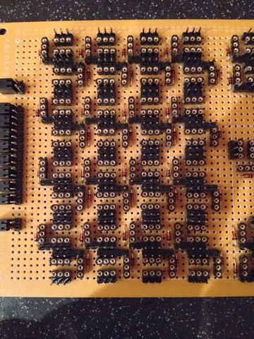
This time around I found that (mercifully) the sockets generally stayed in place whilst I soldered them which saved me holding the socket in place with one hand while dropping a solder blob to anchor one of the pins with the other hand. It seems that if you place the socket correctly first time it’ll stay put but if you move it around at all then it’ll be loose from that point on. With that in mind I managed to get maybe 80% or so of the sockets in first time (which given there’s 123 sockets to place is quite a good thing).
So, on with the pictures:
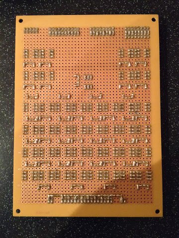
Next job for this board is soldering on the power and ground links and after that it’s wire wrap time. Before that though I’m going to wire up and test the adder circuit on a single bit to make sure the design is OK and works in reality as expected … that also means there’ll be a video again on my next post showing it working (or not perhaps) so that’s something to look forward to ;)