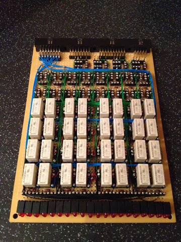
There’s now enough sockets, solder and wires to test all eight bits of the ALU logic card. This isn’t quite a full test as the gating relays that apply one of the results produced by each bit unit haven’t been wired up yet but there’s enough there to be able to set an input and see the results displayed on the LEDs along the front of the card.
So, it’s time to crack out the relays and pop them in the sockets that make up each logic bit unit. There’s four relays needed in each logic bit unit so thats 32 relays in total and this is what it looks like:
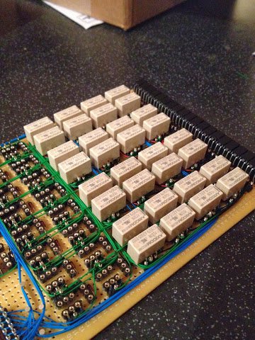
I’ve resisted the temptation to pop the relays in and do tests earlier as I don’t want to risk damaging the relays or sockets by repeatedly inserting and removing the relays. The main idea for using sockets was so I can replace any failing relays in the future but generally once they’re on the board they’re staying there.
With everything set to go I’ve got the test board made earlier plugged in to the B/C input of the card and the power input passed through the test board over to my power supply. Just for a quick reminder the test board looks like this:
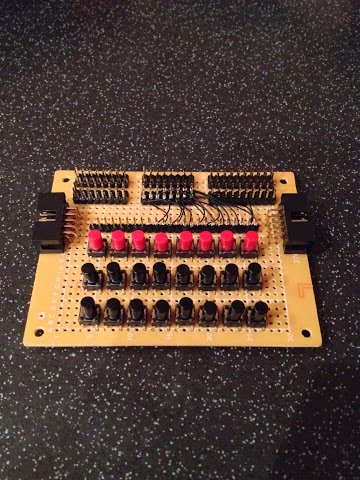
The front row of buttons are configured (via the wire links towards the top of the card) to act as Input B with the middle row set as Input C. On each row of buttons the left most one is bit 7 and the right most is bit 0.
So, the question is … does it all work? Well, I’m delighted (and slightly surprised) to say that yes, yes it does. Want some proof … OK then, here’s a video :)
I’m really starting to feel some progress has been made now and although there’s still so, so, so much to do to finish the complete computer it’s really rewarding to see it actually working as intended. The ALU logic card isn’t quite complete yet so I can’t go for the full celebration just yet — next time I need to wire up the gating relays that select one of the logic results on to the data bus.