8-Bit Move
Copies the content of one 8-bit register to another.
ddd = destination register (000-A, 001-B, 010-C, 011-D, 100-M1, 101-M2, 110-X, 111-Y)
sss = source register (000-A, 001-B, 010-C, 011-D, 100-M1, 101-M2, 110-X, 111-Y)Way back in 2019 I discussed how you can’t ‘half design a PCB’ and that, as a result, my controller cards already have all the required functionality laid down … I just haven’t explained how those ‘missing’ bits of functionality work in this blog yet.
To ensure I was ‘playing fair’ when constructing the controller I only soldered in the relays for the instructions I’d explained in this blog so far. Well, in my Relay Clock Series you may have noticed in the final episode I decided to solder the remaining relays in on the lower controller card meaning … the MOV8, MOV16 and MISC instruction classes are now complete and pretty much raring to go … which means I should probably get on with explaining them.
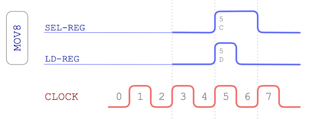
I explained the basics of the 8-bit move instruction previously but its purpose is to copy an 8-bit value from one register to another (yes, copy not move). If the source and destination register are the same then the value in that register is cleared:
Copies the content of one 8-bit register to another.
ddd = destination register (000-A, 001-B, 010-C, 011-D, 100-M1, 101-M2, 110-X, 111-Y)
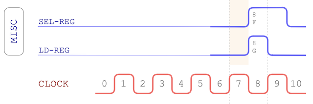
sss = source register (000-A, 001-B, 010-C, 011-D, 100-M1, 101-M2, 110-X, 111-Y)Here’s the MOV-8 timing chart:
By soldering in those remaining relays to the lower controller card I now have registers M1, M2, X and Y available in the list of source and destination registers to pick from. Effectively that means there’s now 64 combinations of register moves possible from this instruction alone. If you exclude moving a register from itself to itself (which clears the register) there’s 56 potential combinations.
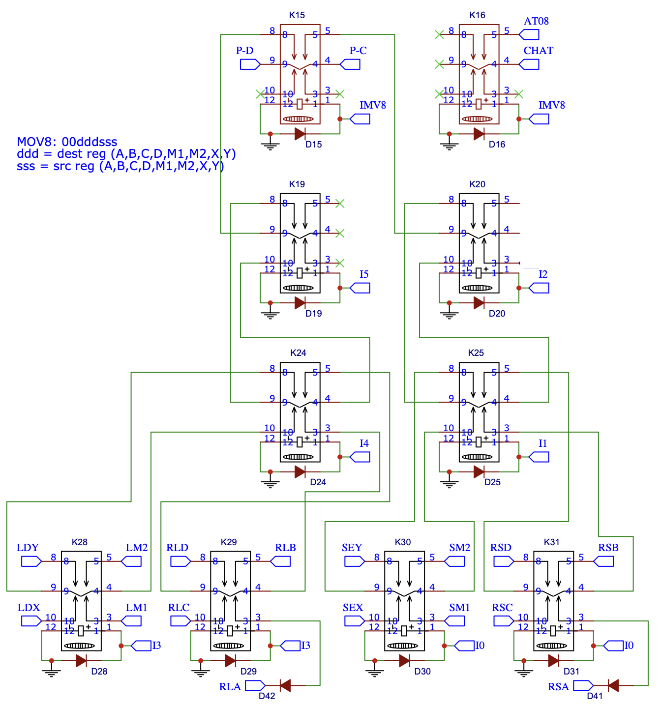
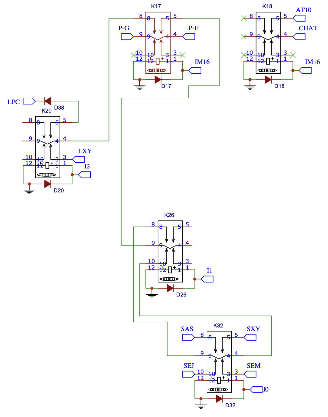
The last time I discussed the schematic for MOV-8 I blanked out the additional relays for brevity and clarity but now I can show the whole thing:
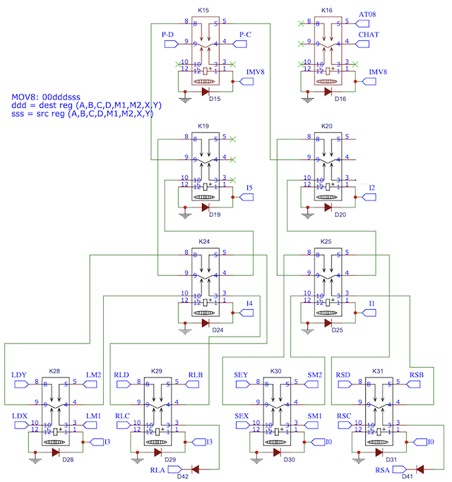
You can clearly achieve a lot of ‘moving’ with the MOV-8 instruction and although you can copy the M register to the XY register by copying M1 to X and M2 to Y in sequence (via the 8-bit data bus) it’d be much quicker, and easier, to have a command that does it all in one go (via the 16-bit address bus). Well, that’s our MOV-16:
Copies the content of one 16-bit register to another.
d = dest reg (0-XY or 1-PC)
ss = src reg (00-M, 01-XY, 10-J, 11-AS)
So, notice there’s some limitations on where you can copy to? This reflects the physical limitations within the computer and registers M and J are read-only by design and so that leaves us with registers XY and the Program Counter (PC) as destinations … which is convenient given we’ve only got 3-bits spare in the instruction to define source and destination.
In terms of sources most are pretty self-explanatory (registers M, XY and J) but what about the ‘AS’ one? Well this refers to the primary switches on the front of the computer and using ‘AS’ (address switches) as a source will gate these to the lower 8-bits of the address bus (with the upper 8-bits set to 0s).
In the architecture of the RC-3 Relay Computer (this computer’s architectural parent) the ‘AS’ source makes more sense as there’s a row of 16 dedicated switches for this purpose. In my design I dropped these for compactness but kept the ‘AS’ source available on the MOV-16 instruction and just gated the 8 primary switches to the address bus instead. As such, in practice, the ‘AS’ source probably won’t get much use in my computer.
Also of note is that setting the Program Counter has an interesting side effect of course … it’ll change where the computer takes its next instruction from. Surely we’ve got jumps for that on the GOTO instruction? Well, yes we have but there’s something special we can do on the GOTO instruction … let’s take a look at it again:
Branches to a given address if stated condition register flag(s) is set. Address of next instruction can optionally be saved in XY register. M register can also be loaded with 16-bit value (without jump).
d = destination register (0-M, 1-J)
s = 1 = load PC if sign bit is set (if negative); 0 = ignore sign bit
c = 1 = load PC if carry bit is set (if carry); 0 = ignore carry bit
z = 1 = load PC if zero bit set (if result is zero); 0 = ignore if zero bit set
n = 1 = load PC if zero bit clear (if result is not zero); 0 = ignore if zero bit clear
x = 1 = copy PC to XY; 0 = no copy
hhhhhhhh = address high byte (to set in M2/J2)
llllllll = address low byte (to set in M1/J1)
There’s the option (in the last bit x of the opcode) to store the location of the next instruction in memory (right after the
GOTO instruction itself) into the XY register before taking the jump. Why would you want this? Well, it gives you the
opportunity to come back to where you jumped from after whatever you’ve jumped to has finished. To come back we just copy the
address in the XY register back to the Program Counter (with a MOV-16 10100101). This effectively behaves as a ‘return’
instruction and in my assembly language rts maps to 10100101 accordingly.
Actually, whilst we’re talking of ‘instructions within instructions’ there’s a hidden one within the GOTO too. If you execute a
11000000 it’ll load the M register with the next 16-bits of memory without taking any jumps. Effectively this makes it a
form of ’load immediate’ allowing a 16-bit value to be loaded directly in to the M register. Variant 11100000 does the same
trick but loads the J register. Arguably that’s less useful as the J register is write-only from the data bus and
read-only to the address bus so all you can then do is copy it to XY or PC via a MOV-16 instruction.
Anyho, let’s take a look at the MOV-16 timing chart:
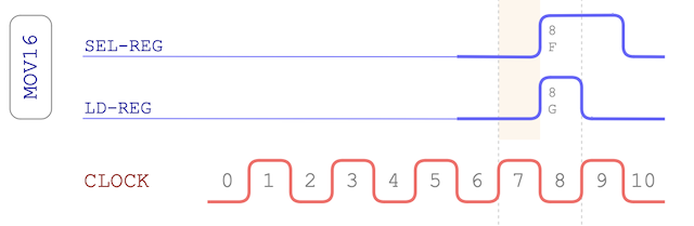
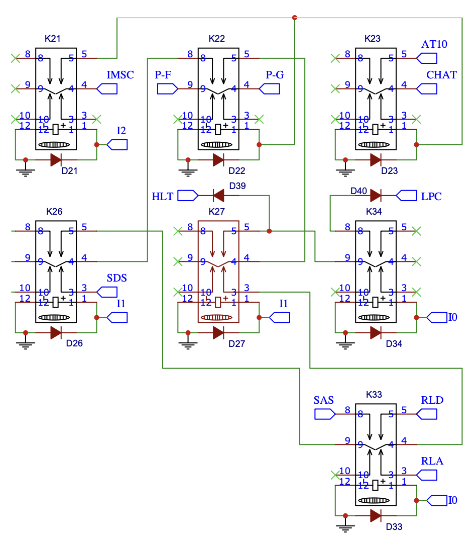
… and in terms of the schematic it’s not too dissimilar to what we saw earlier for MOV-8 …
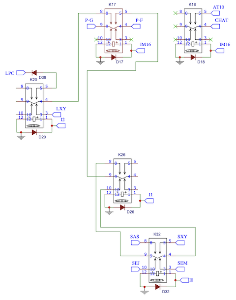
The reason for the ‘odd layout’ of this schematic is because the MOV-8 and MOV-16 schematics share the same page and so fit around each other as you’ll see later.
So, that leaves us with just one instruction class left for this post:
Ah yes, the instruction class that covers ’everything’ else. In this case anything starting with 10101 will be classified
by the decoder as belonging to the MISC class (similarly to the way anything beginning 10100 belongs to the MOV-16 class).
With the first 5 bits taken for classification that leaves us 3-bits spare for some more instructions:
Loads the value set on the front panel switches into register A or D.
d = destination register (0-A, 1-D)Halts execution of the program (optionally reseting the program counter from the front panel switches).
r = reload program counter (0-no reload, 1-reload from switches)Load switches is pretty straightforward and is very similar to the ‘AS’ source of MOV-16. In this case the same primary switches will be gated to the data bus and then loaded to the A or D register. This gives a nice handy way of getting input from the user … especially when combined with the second instruction above.
Halt does ‘what it says on the tin’ - it halts the computer. If you’ve seen my last video you’ll also know it additionally rings a bell to let you know it’s halted (as if the silenced relays isn’t enough to give it away). When the computer is in the halt state, and with the last bit of the instruction set to 0, the program counter will stay pointing at the next instruction in memory. If you follow the halt with a ’load switches’ instruction you’re effectively waiting for the user to set the input switches. Once done so they can release the halt with the ‘restart’ switch.
If the last bit of halt is set to 1 then it’ll load the program counter (lower 8-bits again just like with MOV-16s ‘AS’). Again, this is a bit of a hang over from the RC-3 design where loading from the dedicated address switches was handy for re-starting a demo program from a location in memory. Here in my computer it’ll likely not get used much.
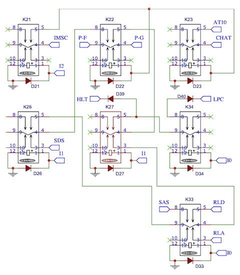
The timing chart is remarkably similar to the MOV-16 one …
… and in many ways it is although sometimes it won’t do the register select part and sometimes it won’t do the register load part (all depending on exactly what the instruction requires). In either case though the ‘potential’ timing diagram remains the same. The schematic for MISC makes this more explicit:
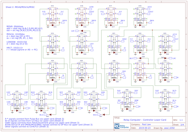
That’s it … we’ve finished off the MOV-8 instruction class and added two new ones. As I alluded to earlier on in this post all three of these instruction classes fit nicely in to the same area of the controller PCB and so the schematic follows suit. To finish off then, below is the full schematic for the MOV-8, MOV-16 and MISC instructions: