Load Immediate
Loads a value between -16 and +15 in register A or B.
    r = destination register (0-A, 1-B)
ddddd = value (-16..15)In my last post I covered off the controller design for the GOTO instruction. Being as I’ve decided to implement the controller on a new set of PCB cards I need to transfer over the existing ALU, MOV8 & SETAB instructions to the new controller design. At the relay level nothing really changes so I’ll just quickly recap the timing and implementations here using the new schematic style and then in my next post I can move on to putting the full controller schematic and PCB design together.
Let’s cover the three instructions off in order of complexity:
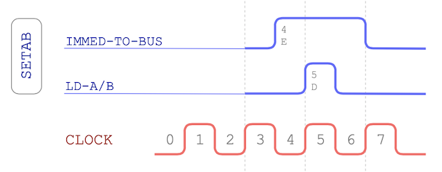
The SETAB instruction loads an immediate value in to either the A or B register. This is a really useful and quick way to get a value loaded in ready for performing further ALU calculations. The value to be loaded is limited though due to the number of available bits in the instruction opcode:
Loads a value between -16 and +15 in register A or B.
r = destination register (0-A, 1-B)
ddddd = value (-16..15)Here’s the associated timing chart for the SETAB instruction:
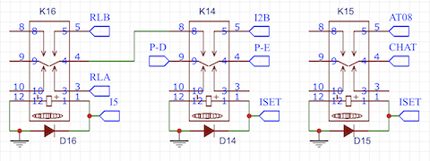
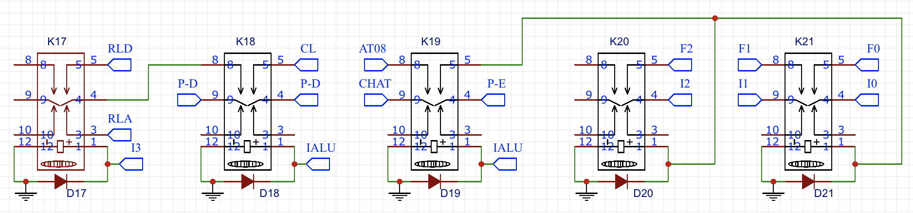
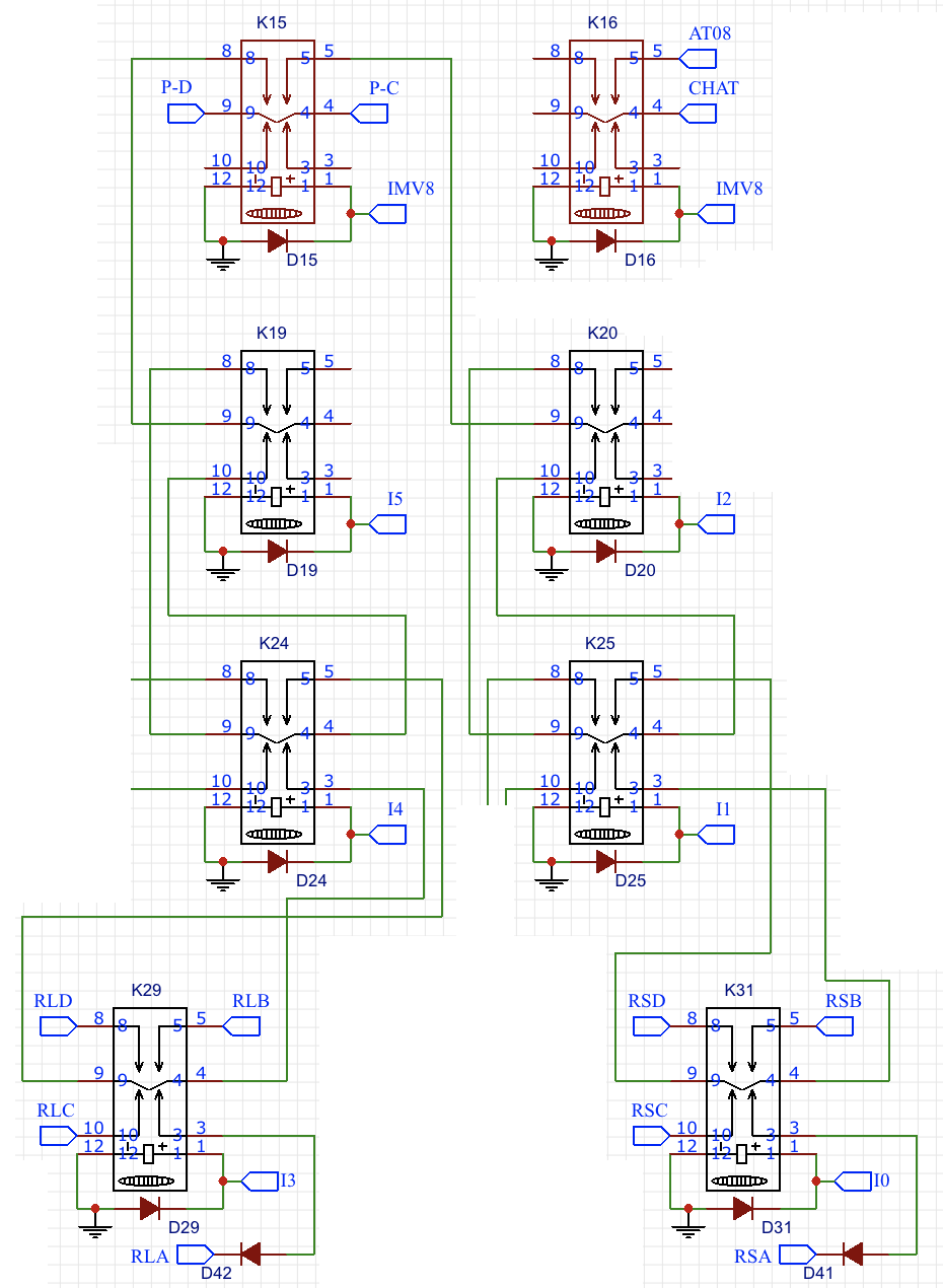
This is all very straightforward to implement in relays:
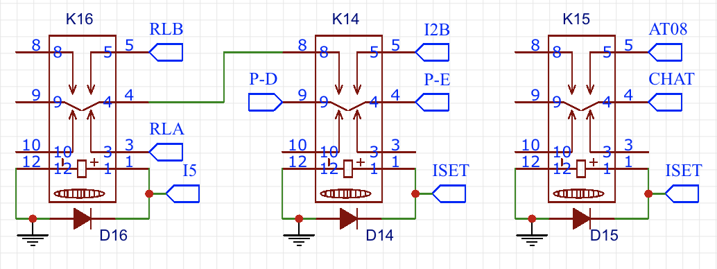
The only thing that perhaps needs a brief explanation is the CHAT line on the right. This is activated early in the fetch/increment cycle to indicate that the sequencer can now have an abort line set if required. All of the instructions on this page are 8-cycle and each of the instruction schematics will set AT08 when the CHAT line is active.
The ALU instruction can perform a number of arithmetic and logic operations on the B and C registers (or just the B register for operations that only work on one value). The result of the operation can be placed in either the A or D register.
Performs an arithmetic or logic operation on the B (and optionally C) register(s).
r = destination register (0-A, 1-D)
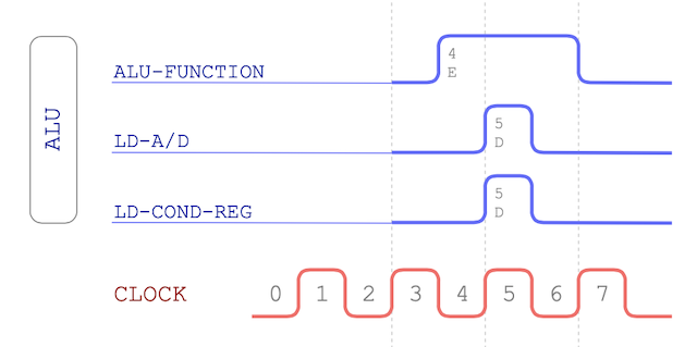
fff = function code (000-NOP, 001-ADD, 010-INC, 011-AND, 100-OR, 101-XOR, 110-NOT, 111-SHL)The timing chart for the ALU instruction looks like this:
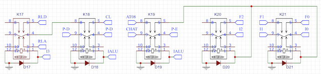
The relay schematic for ALU uses five relays over SETAB’s three but is still easy to understand:
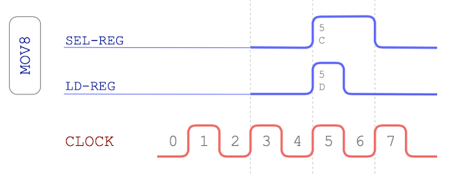
The ’not so aptly’ named MOV8 instruction copies an 8-bit value from one register to another. If the source and destination register are the same then the value in that register is cleared:
Copies the content of one 8-bit register to another.
ddd = destination register (000-A, 001-B, 010-C, 011-D, 100-M1, 101-M2, 110-X, 111-Y)
sss = source register      (000-A, 001-B, 010-C, 011-D, 100-M1, 101-M2, 110-X, 111-Y)
Here’s the MOV-8 timing chart:
The schematic for MOV-8 has a lot more relays going on but mostly that’s around decoding the source and destination registers for the operation:
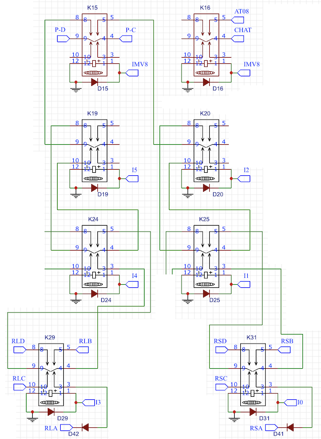
You can see there’s quite a few bits of this schematic blanked out. I’ve done that for brevity here but effectively that’s where the M1, M2, X and Y registers can be selected as a source or destination. I won’t be implementing those for the moment although as you can probably tell they’re just a couple of relays away.
That it for these instructions. In my next post I’ll bring these together with the GOTO instruction and get the full controller schematic laid out and design the PCB lay out too and then I’m ready for some more board construction.