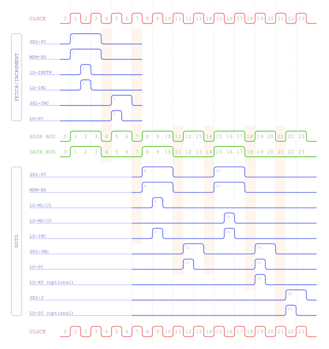
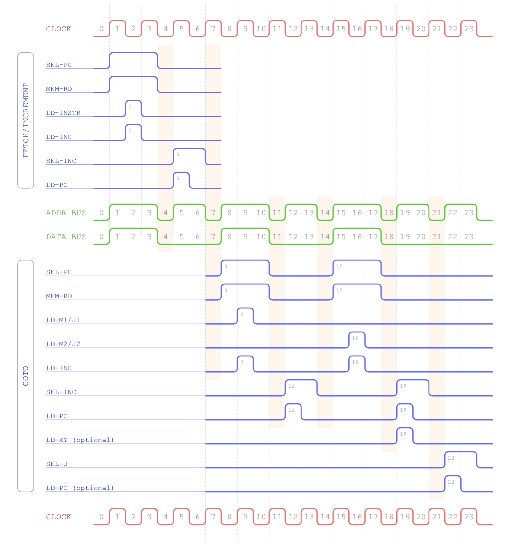
Recently I’ve been looking at what’s needed to implement branching in my computer (the upcoming GOTO class of instructions). In my last post I covered the timing chart for the GOTO class which is repeated below:
To achieve this timing I’ll need a sequencer that can ‘count’ up to 24 (currently it only goes up to 8). Actually none of this is too difficult as counting beyond 8 more-or-less repeats the same pattern of relays. If you’re not familiar with how the current 8 cycle sequencer works then it’s well worth reading the post on that which goes in to more detail around how the FSM (finite state machine) works.
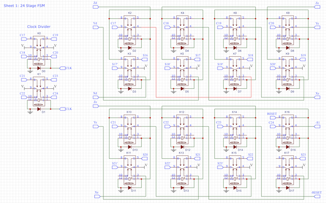
As mentioned I’ve already got an 8-cycle sequencer which is built using wire-wrap, sockets and the matrix boards. Given I’ve already taken the leap in using professionally manufactured PCBs now I’ll follow suit here and re-design the full sequencer from scratch. Transferring the existing 8-cycle design in to EasyEDA we get the following:
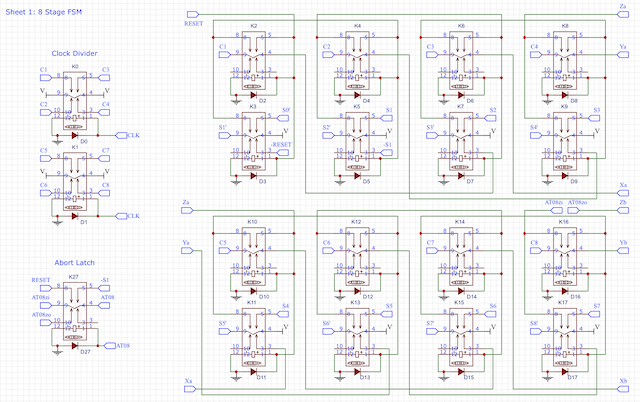
I’ll add a link later in this post to a nice PDF version of these diagrams so you can take a closer look should you wish to. Note though that this is the exact same circuit as before … it’s just laid out differently. To keep the diagram cleaner I’ve put the clock divider at the top left and the abort-8 relay at the bottom left. You can then see the main ring counter is to the right. Note that the abort-8 latch is there to interupt the FSM chain when needed … if the latch isn’t set then the counter continues on to 10-cycles and 12-cycles as follows:
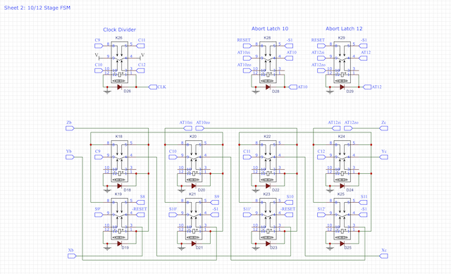
So, this is another 4 stages of the ring counter with abort relays at the 10 and 12 cycle mark. Similarly we can add another 4 stages to get to the 16 cycle mark:
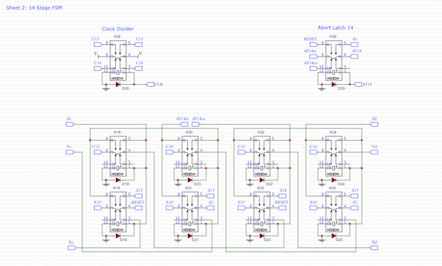
Here we’re adding an abort relay at stage 14. These aborts at 8/10/12/14-cycles aren’t placed arbitrarily of course … these are the exact lengths of the various instruction classes I’ll be implementing in the computer. So far we only have 8-cycle instructions implemented but there will be 10, 12 and 14 cycle ones coming up.
All that remains to do then is repeat the ring counter pattern all the way up to 24 cycles:
Note that no abort relay is required in this portion of the FSM as at the end of the chain we just active the RESET line directly which will restart the sequencer back from stage 0.
As mentioned above you can find a PDF version of these schematics here.
So, that gives us something that can count to 24 but how does that help us get the timing pulses for the GOTO instruction? Well, lets take a look at the outputs of the 24-cycle FSM:
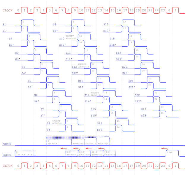
You might be able to spot that some of the outputs are exactly what we’re looking for … they’re the right pulse for the right duration of time. Some of the pulses we need though can be obtained by combining the outputs together. This is what I call ‘pulse distribution’ and I’ll cover that off in my next post … and combining the FSM with the pulse distribution gives us the sequencer as a complete unit.