With the sequencer now designed and constructed I’m much closer to getting branching working on my relay computer. The next
hurdle is updating the controller cards so that they can fire the appropriate control lines at the right time as directed
by the sequencer pulses. As a reminder here’s the GOTO instruction itself:
Branch/Call & 16-bit Load Immediate
GOTO24
11dscznx
hhhhhhhh
llllllll
Branches to a given address if stated condition register flag(s) is set. Address of next instruction can optionally be saved in XY register. M register can also be loaded with 16-bit value (without jump).
d = destination register (0-M, 1-J)
s = 1 = load PC if sign bit is set (if negative); 0 = ignore sign bit
c = 1 = load PC if carry bit is set (if carry); 0 = ignore carry bit
z = 1 = load PC if zero bit set (if result is zero); 0 = ignore if zero bit set
n = 1 = load PC if zero bit clear (if result is not zero); 0 = ignore if zero bit clear
x = 1 = copy PC to XY; 0 = no copy
hhhhhhhh = address high byte (to set in M2/J2)
llllllll = address low byte (to set in M1/J1)
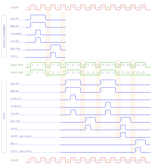
… and here’s the associated timing chart to be implemented …
The fetch/increment cycle is already catered for as it’s common to all instructions but here’s the schematic for that:
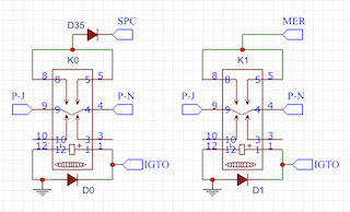
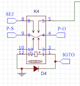
So let’s start off with an easy part of the GOTO operation. The first two lines of the timing diagram select the program
counter (SEL-PC) and read the memory (MEM-RD) which will put the second and third byte of the instruction on to the data bus.
This happens at pulse J and N and is easily implemented with a couple of relays:
Note that there’s a diode in the SPC (SEL-PC) output as back-feeding could inadvertently drive the P-J or P-N line causing
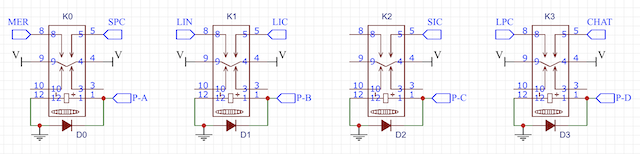
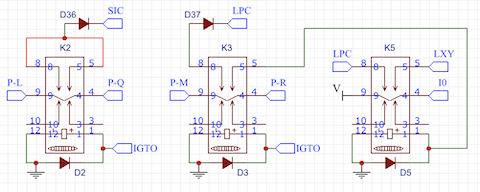
erratic behaviour. With the 2nd/3rd byte of the instruction available on the data bus we then need to load these into either
the M or J register based on bit 5 of the opcode. Whilst that’s going on we also load the incrementer (LD-INC) ready to move
the program counter on.
Next we need to select the incrementer and put the value back in the program counter. Optionally at the last increment of
the instruction we can also load the XY register effectively storing the address of the next instruction in memory. This is
used as a ‘return address’ should we want to continue execution from where we initially took a jump from. Bit 0 of the
instruction sets this option.
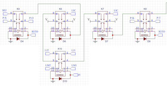
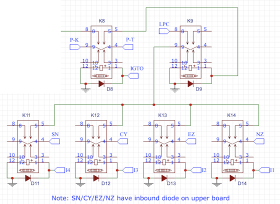
Timing wise that’s the bulk of the chart done - we’re just left with the last two lines SEL-J and the optional LD-PC. This is
where we’re gating the address held in the J register to the address bus and then if a jump is required we load the program
counter. The SEL-J is easy enough:
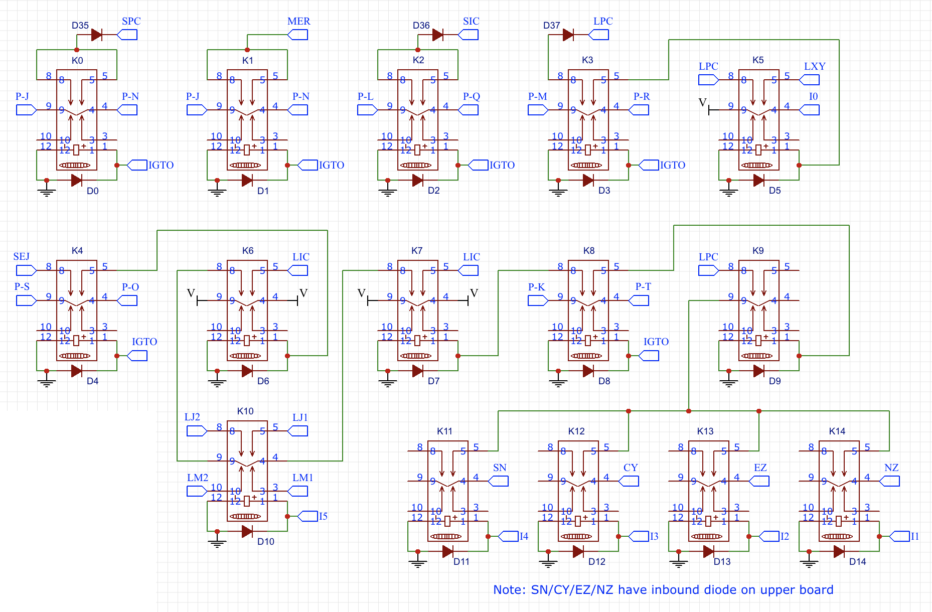
The decision to jump or not is based on the condition registers and bits 1, 2, 3 and 4 of the instruction and takes a bit more
relay logic to wire out:
Again, we have to be careful not to back-feed to the condition registers so there’s a diode on each of the incoming lines but
it’s not shown on this schematic.
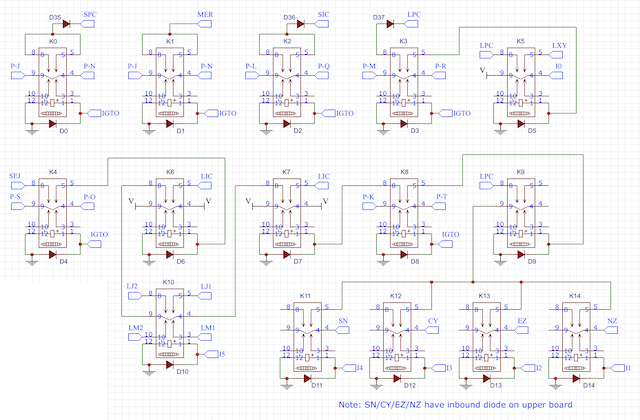
As mentioned in my last post I’m going to rebuild the controller cards on PCBs which will mean also re-implementing the ALU,
MOV8 and SETAB instruction classes. I’ll cover off the design of these in my next post then get them ordered in and
constructed.