In my last post I covered the design for the GOTO opcode which will enable my relay computer to perform branching, loops and so on. Here’s where I got to last time:
Branch/Call & 16-bit Load Immediate
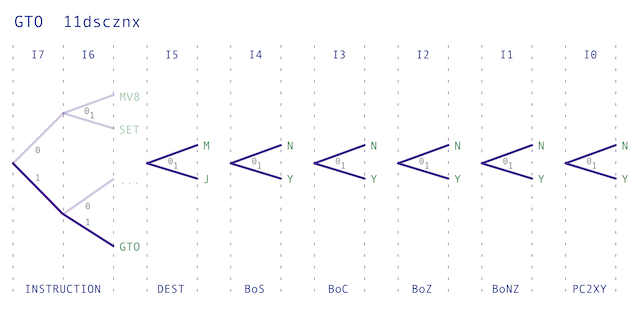
GOTO24
11dscznx
hhhhhhhh
llllllll
Branches to a given address if stated condition register flag(s) is set. Address of next instruction can optionally be saved in XY register. M register can also be loaded with 16-bit value (without jump).
d = destination register (0-M, 1-J)
s = 1 = load PC if sign bit is set (if negative); 0 = ignore sign bit
c = 1 = load PC if carry bit is set (if carry); 0 = ignore carry bit
z = 1 = load PC if zero bit set (if result is zero); 0 = ignore if zero bit set
n = 1 = load PC if zero bit clear (if result is not zero); 0 = ignore if zero bit clear
x = 1 = copy PC to XY; 0 = no copy
hhhhhhhh = address high byte (to set in M2/J2)
llllllll = address low byte (to set in M1/J1)
The opcode can also be drawn in diagram form as follows:
As mentioned in my last post this is by far the most complicated opcode to date … and in fact, this will be the most
complicated opcode the computer is going to get. The next job is to take the design above and derive some timing diagrams to
show which control lines will be operated at what time so that the opcode functions as desired. Before we get stuck in lets
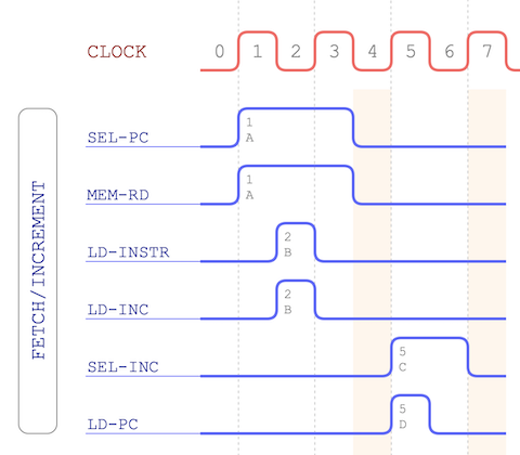
remind ourselves of what happens at the beginning of all opcodes:
This is the ‘fetch/increment’ cycle which loads the opcode in to the instruction register and then moves the program counter
on to the next instruction in memory. In the case of GOTO we have three bytes … the opcode itself followed by a 16-bit
address to potentially jump to. This means that after the fetch/increment the program counter is now pointing to the lower
8-bits of that 16-bit address.
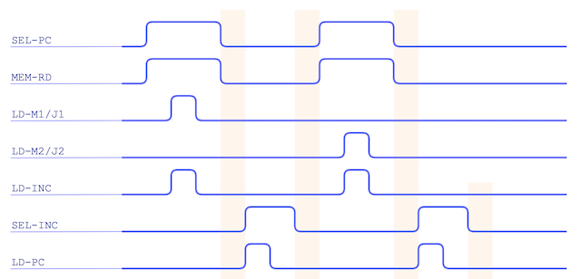
So, what’s needed is to load that in to either M1 or J1 and increment the program counter once
again. That gets us pointing to the upper 8-bits of the address so we repeat similarly to load either M2 or J2 and increment
one last time. That finally gets us in to the state where the program counter is pointing to the next instruction just like
any other opcode would. If we do decide to make the jump to the given address we’ll re-point the program counter otherwise
we’ll continue as normal. Let’s do a basic map of this:
All this, of course, needs to happen after the initial fetch/increment as the address and data busses will be busy during that
time. We’ll also leave a gap between those operations to ensure any required busses are clear.
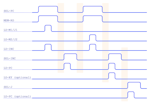
Timing wise that covers most of the heavy lifting for this opcode. With the program counter pointing to the next instruction in memory we can optionally load the XY register from that so we can return back from a jump (the last bit of the opcode
tells us if this is wanted or not). Finally we need to decide to take the jump itself or not. The jump address
will have been loaded in to the J register (jumps from M aren’t supported) and all we need to do, if we are jumping, is copy
that value to the program counter meaning the computer will continue execution from the given address. Here’s the timing with
these last two steps added in.
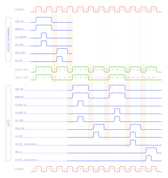
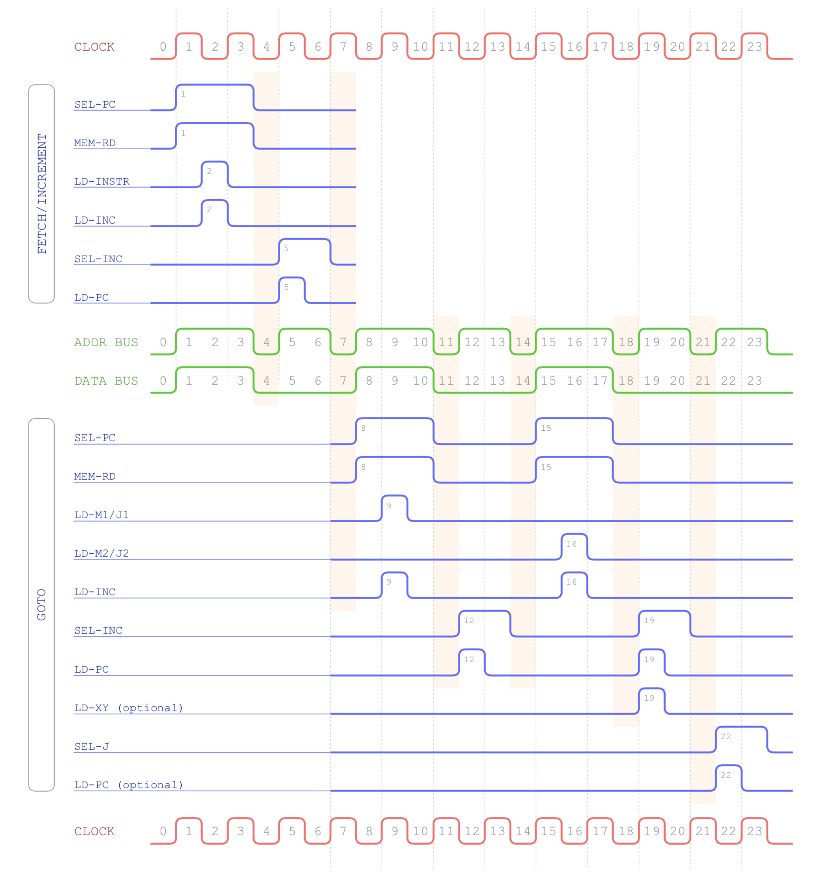
Putting everything together we end up with the final GOTO timing chart:
So, we now know what needs to happen and when but how does this get implemented in the computer? Well, just as with the other
instructions, you look at the timing diagram and pick out the common pulse shapes which we can create in the sequencer. The
controller will then use these pulses to operate the control lines as per our timing diagram.
So far the sequencer counts up to 8 ticks of the clock (each tick being a rising or falling edge of the clock signal). That’s
been enough to operate the instructions created so far given I’ve been able to utilise the data bus whilst the address bus is
finishing off the increment of the program counter. In this particular case I’ve got to wait for all that to happen and even
then I’ve got to cycle through the next two bytes of the instruction. All in all I’ll need to go all the way up to 24 ticks
to fit this instruction in.
Given this is the longest instruction it’s probably about time to finish off the sequencer design so that it can produce the
pulses for not only this instruction but all the others I’ll be implementing. That certainly deserves its own post so I’ll
cover that off next time.