ALU Operation
Performs an arithmetic or logic operation on the B (and optionally C) register(s).
  r = destination register (0-A, 1-D)
fff = function code (000-NOP, 001-ADD, 010-INC, 011-AND, 100-OR, 101-XOR, 110-NOT, 111-SHL)There’s been a common theme recently in the comments on my YouTube videos … people are ready to see my relay computer gain the power of branching and become a ‘proper’ computer … and that’s fair enough because that’s the point where the computer can do way more interesting things and run more complicated programs. Originally I was going to add new instructions to the computer in order of complexity but I don’t want to keep you (or I) waiting for the ‘main event’ any longer so it’s time to start designing the most complicated of all instruction classes … the ‘GOTO’.
Let’s start of by defining what we want to achieve with this new ‘GOTO’ instruction class:
For the conditional jumps we can use the ALU condition register which provides some feedback on the last ALU operation performed. The condition register has three flags, set/cleared after each ALU operation, as follows:
| Flag | Id | Meaning |
|---|---|---|
| Carry | C | set when a bit is carried in the arithmetic unit (which can also indicate arithmetic overflow depending on the interpretation of the numbers being added) |
| Zero | Z | set when the ALU result is zero (all bits are off) |
| Sign | S | set when the most significant bit is set (which would indicate a negative result for signed values). This condition has no direct meaning for unsigned numbers (other than indicating the number has a value of 128 or more). |
For convenience I’ll also design a ‘virtual’ flag for when a result is not zero … this is simply the opposite of the zero flag. So, what sort of conditional branching logic can we achieve with the (C)arry, (Z)ero, (N)ot-Zero and (S)ign flags?
As well as reacting to individual condition flags we can also combine flags together to create more interesting combinations. If we build a truth table where ‘0’ means ignore that flag and ‘1’ means the flag must be set with multiple ‘1’s meaning at least one of those flags must be set (OR combination) we get the following:
| S | C | Z | N | Meaning |
|---|---|---|---|---|
| 0 | 0 | 0 | 0 | Never branch (arguably not that useful) |
| 0 | 0 | 0 | 1 | Branch if result not zero (can test for inequality following B XOR C) |
| 0 | 0 | 1 | 0 | Branch if result zero (can test for equality following B XOR C) |
| 0 | 0 | 1 | 1 | Always branch (unconditional branching) |
| 0 | 1 | 0 | 0 | Branch if carry (useful after ADD or INC operation) |
| 0 | 1 | 0 | 1 | Branch if carry or not zero |
| 0 | 1 | 1 | 0 | Branch if carry or zero |
| 1 | 0 | 0 | 0 | Branch if sign bit set (can test for B < C following B ADD -C) |
| 1 | 0 | 1 | 0 | Branch if sign bit set or zero (can test for B <= C following B ADD -C) |
| 1 | 1 | 0 | 0 | Branch if sign bit set or carry |
So, we can see that from the table above we now have 4-bits of our GOTO opcode (sczn) and that fulfils our first two
requirements (conditional and unconditional branching). To implement our third requirement (store ‘return’ address) we
just need a flag to indicate if the XY register should be loaded with the address of the next instruction in our
program before taking a jump … this takes us to 5-bits of our GOTO opcode (scznx) where x means copy PC -> XY register
when set.
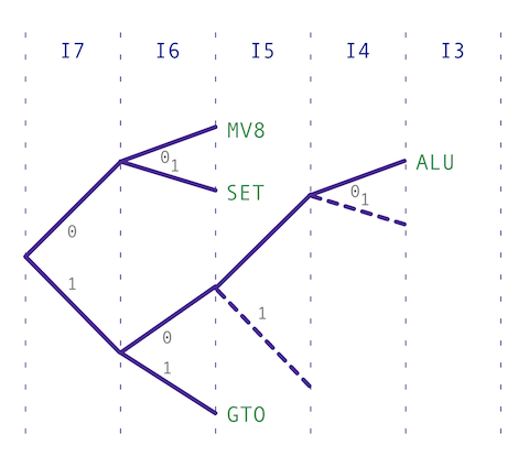
In designing our GOTO opcode we need to prefix it with a sequence of bits that allow the decoder to work out what class of instruction it’s currently dealing with. Given we’ve already used up 5-bits we’ll need to keep the prefix breif … here’s the classes we have so far:
Performs an arithmetic or logic operation on the B (and optionally C) register(s). Copies the content of one 8-bit register to another. Loads a value between -16 and +15 in register A or B.ALU Operation
r = destination register (0-A, 1-D)
fff = function code (000-NOP, 001-ADD, 010-INC, 011-AND, 100-OR, 101-XOR, 110-NOT, 111-SHL)8-Bit Move
ddd = destination register (000-A, 001-B, 010-C, 011-D, 100-M1, 101-M2, 110-X, 111-Y)
sss = source register      (000-A, 001-B, 010-C, 011-D, 100-M1, 101-M2, 110-X, 111-Y)
Load Immediate
    r = destination register (0-A, 1-B)
ddddd = value (-16..15)
Note that I haven’t implemented the MOVE-8 class ability to use the M1/M2/X/Y registers yet … that’ll need wiring out now the new register cards are complete. It’s also worth noting that we’re missing a MOVE-16 instruction class to move values between the XY, M, J and PC registers … this’ll also come later and will be needed to ‘return’ from a branch where we’ve stored the return address in XY (effectively a 16-bit copy from XY -> PC).
Given what’s already used in the above table we can prefix our GOTO class with 11 leaving room for other upcoming
instructions starting with 10. With all our instruction classes to-date we get the following decoder mapping:
Using the 11 prefix gives us 1-bit spare in the opcode which we can use to implement an additional useful operation. Following every GOTO opcode there’ll need to be a 16-bit address which will be loaded in to the J register and then if a
jump is required that value is copied into the program counter making execution carry on elsewhere in the program. What
would also be useful is to be to load the M register in a similar way (but without taking any jumps as J would be in an
unknown state). As it happens the sequencing and control for both these instructions are very similar so by adding a
destination flag to specify if we load J or M with the given address we get our final opcode form:
Branches to a given address if stated condition register flag(s) is set. Address of next instruction can optionally be saved in XY register. M register can also be loaded with 16-bit value (without jump).
d = destination register (0-M, 1-J)
s = 1 = load PC if sign bit is set (if negative); 0 = ignore sign bit
c = 1 = load PC if carry bit is set (if carry); 0 = ignore carry bit
z = 1 = load PC if zero bit set (if result is zero); 0 = ignore if zero bit set
n = 1 = load PC if zero bit clear (if result is not zero); 0 = ignore if zero bit clear
x = 1 = copy PC to XY; 0 = no copy
hhhhhhhh = address high byte (to set in M2/J2)
llllllll = address low byte (to set in M1/J1)
To put that in to context here’s some example GOTO opcodes:
| Opcode | Instruction |
|---|---|
11100100 | Branch to the following address if ALU result was zero |
11100010 | Branch to the following address if ALU result was non-zero |
11101000 | Branch to the following address if ALU result had carry |
11110000 | Branch to the following address if ALU result was negative |
11100110 | Branch to the following address (unconditionaly) |
11100111 | Call to the following address (unconditionaly & storing return address in XY) |
11000000 | Load the following address in to M |
So, that’s the opcode sorted and the hard work begins. As you can see there’s a lot going on with this instruction … we need to load a 16-bit address into either the M or J register, optionally copy the PC to the XY register, inspect the ALU condition register and decide if we’re going to jump and if so copy J into the PC. This is by far the most complicated instruction class so far … way beyond the simple SETAB, ALU and MOV-8 operations seen so far.
In my next post I’ll design the timing diagrams for the GOTO opcode so we can define which control lines of the computer need operating when. That’ll also lead to a serious upgrade for the sequencer and controller cards so I’ll cover that in subsequent posts too.