In my last two posts I covered the construction of the upper and lower incrementer cards. The lower card is a 16-bit half adder and the upper card is a 16-bit register. Together they form the incrementer unit as a whole which can add one to whichever value is currently on the address bus and then hold that value ready for pushing back out to the address bus. More often than not the incrementer will be used to push the program counter on one place but in theory it can be used to increment any value put on the address bus.
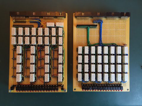
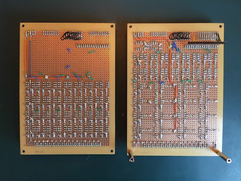
Here are the two incrementer cards side-by-side:
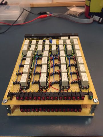
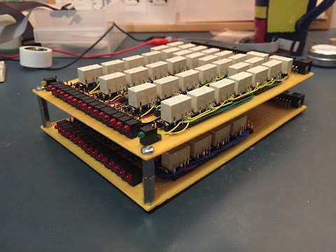
… and when stacked together they look like this …
As in my other ‘completion’ blog posts I’ve put together a video which gives an overview of the incrementer and shows it in use:
With the incrementer unit now complete we’re incredibly close to a computer that can step through a program held in memory. The last step is to update the sequencer and control units to implement the fetch and load cycle. This will load the current instruction pointed to by the program counter into the instruction register and then the program counter is incremented to point at the next instruction.