This is a bit of a landmark moment … at least for the construction of my relay computer. For a long time now my blog posts have been leading up to the point where my computer will execute a program in memory without any further input from the user. Well, it’s this post where that finally happens and all that stands in the way is a tweak to the sequencer and an addition to the controller unit. Here I’ll just stick to the pictures (and a video of course) but the design of the sequencer/controller changes is covered in this previous post.
Right, let’s start with the sequencer. We need to pull off two new pulses (A and B) from the 8-cycle finite state machine and with the changes in place the sequencer now looks like this:
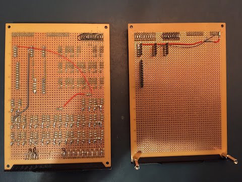
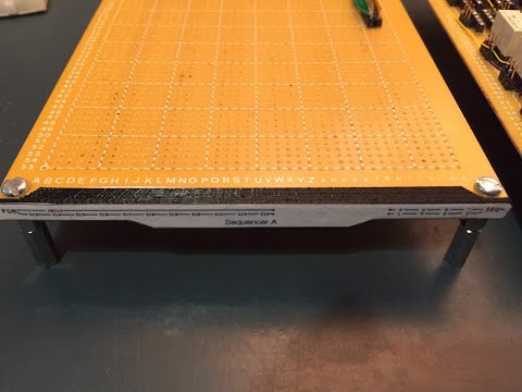
You’ll be forgiven for not spotting the changes straight away (doubly so if you’ve not been following my blog). The sequencer gains two LEDs to show the new pulses (on the lower card) but other than that it’s just wire links. The two cards close up look like this:
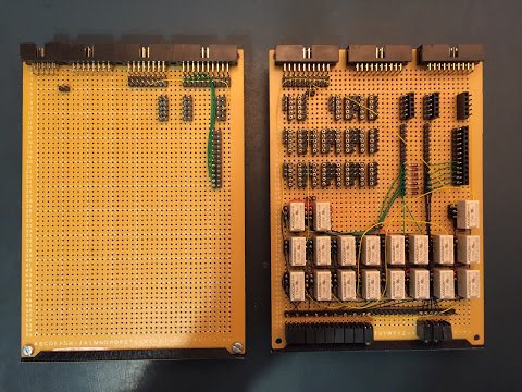
That’s it for the sequencer … the changes on the controller cards are a bit more involved:
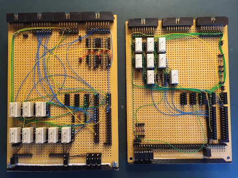
On the upper card (shown on the left when viewed from the front) there is a group of four relays in the top right of the card … although for some reason I took the photo before popping the relays in their sockets. These four relays take the pulses A, B, C and D and use them to fire the control lines at the right time to implement the fetch and increment cycle. As it happens some of these control lines leave the controller on the upper card and some on the lower card. This means more card interconnects are needed which are added in the middle of the card.
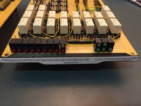
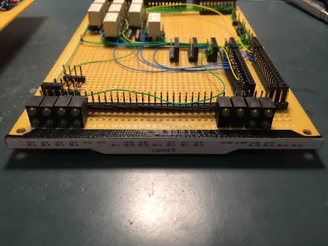
A close up photo of the front of the cards shows the newly added LEDs:
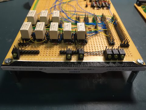
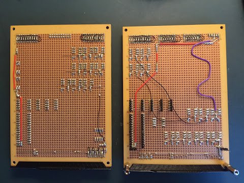
The upper card gains the Memory Read LED whilst the lower card gains Load Instruction, Program Counter Select/Load and Incrementer Select/Load. All five of these control lines are fired as part of the fetch and increment cycle. Here’s a close up of the LEDs viewed from the rear side:
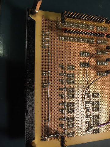
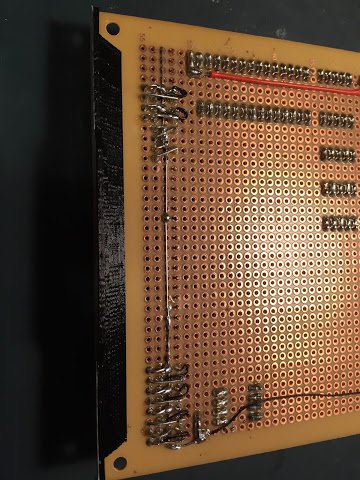
You can see that much of the header strip is not soldered down yet and this is because as the controller gains more functionality there’ll be more LEDs added. Actually, the photos of the LEDs viewed front on give the game away a bit as the legend strip shows what the upcoming LEDs will be for.
So, I’ve been deliberately brief in this post sticking mainly to some close up photos and that’s because I’ve gone to the time and effort of making a ’lovely’ video. The video covers the changes to the sequencer and controller but more importantly shows the computer running through a program - the ’landmark moment’ mentioned at the top of this post. Here’s that video:
As I mention at the end of the video there’s a lingering question of what’s next. Well, as I said, it’s a pain to enter a program in to the computer at the moment so it’s time to make use of the remaining primary switches to automate the ‘store instruction cycle’ effectively doing something similar to what the fetch/increment cycle does but loading the memory from the primary switches rather than loading the instruction register from memory. One’s that’s all done (and I’ve blogged about it and made another ’lovely’ video) then I’ll cover the instruction set as it currently stands and then I think it’s time to have a review of the progress on the computer to date and reflect on what’s been achieved so far.
In the meanwhile though I think a small celebratory drink is in order.