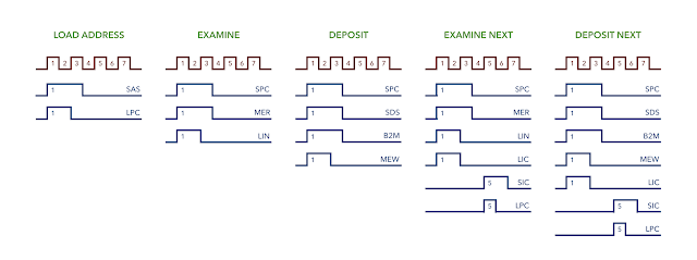
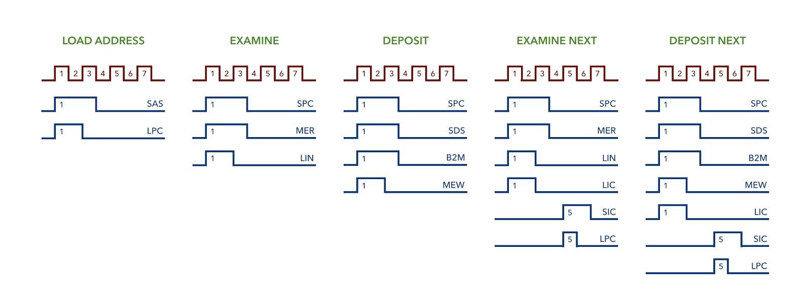
In my last post I made a start on the auxiliary control design which once completed will make it much easier to load instructions in to memory - effectively it’s a computer within a computer. If you haven’t read my previous post then it’s definitely worth doing so as this post picks up where that one left off. As a reminder though we’re looking to perform the following operations:
… which can be derived from the following pulses …
To make those pulses though we’re going to need a clock signal (which is shown in red in the diagrams above). In the main computer the timing signal drives the sequencer and it’s from there where the pulses are then derived. As mentioned in my last post it turns out that we can take a shortcut and do without a sequencer in this case but to explain why I’ll need to start with how you make a clock signal out of relays … well, relays and a few other components. Be warned though, this is going to be one of my longest posts yet as there’s a lot to get though.
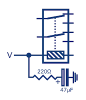
So far all of the relays in the computer react directly to the signal feeding them … if power comes down the line then the relay switches on and if the power gets cut then the relay switches off. The lines coming out of that relay then typically go on to drive other relays and it’s the combinations of these relays that make up the various units of the computer. You can probably see that if you could hold a relay on for a short period after the power is cut then you could string a chain of these ‘delay’ relays together and you’ve got a basic clock circuit. An easy way of creating this delay is by the use of a capacitor which can store a charge when the relay is receiving power and then discharge through the relay when the power is cut. Schematic wise it looks like this:
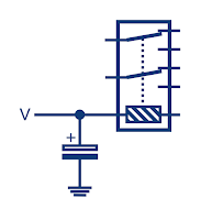
In this circuit when the power is applied the relay switches on and the capacitor charges up. Although not shown in the diagram the other side of the relay coil also goes back to ground. When the power is removed the capacitor will discharge through the relay and off to ground which will keep the relay switched on until the capacitor is drained. Unsurprisingly however that’s a lot more to it than that and this is the first place in the computer where we’re going beyond power being either connected or disconnected. Let’s first look at how capacitors behave when charging and discharging:
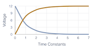
This graph tells us that after 5 time constants the capacitor would be 99.2% charged and in the specific case where we’re working with 12V it would have reached 11.92V. When discharging the curve is flipped and after 5 time constants the capacitor would have reached 0.08V. So, how long is one time constant? Well, it depends on the capacitor and the resistance of the circuit the capacitor is charging in. One time constant is defined as R times C … that is, the resistance measured in ohms times the capacitance measured in farads. So let’s take the example where we have a circuit with 100 ohms resistance and a 470 micro-farad capacitor ( a farad is a very big unit so capacitors are typically in the micro-farad range):
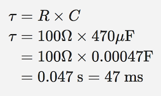
Therefore it would take 5x47 = 235ms for the capacitor to reach 99.2% charge in this case. Discharge works similarly and with a fully charged capacitor it would reach 0.08V after 235ms of discharging through a circuit with a 100 ohm resistance. So what about our simple relay circuit above? Well, looking at the data sheet for the 12V relays I’m using we can see that the coil has an internal resistance of 1029 ohms. Just as above we can pop that value in to the formula to get our time constant:
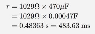
From this we can therefore calculate that it would take 5x0.48363 = 2.42s for the capacitor to drain down to 0.08V. It’s worth stating here that the real time value would differ slightly as the coil won’t be exactly that resistance and the capacitor won’t be exact either but it’s good enough for our purposes. Taking another look at that data sheet we can see that the release voltage is 1.2V, that is, if the relay is already activated the voltage could drop all the way down to 1.2V before the relay deactivates. So, next question is when would the capacitor reach this value? Well, that requires a slightly more complex formula:
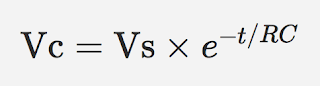
Here Vc is the voltage across the capacitor, Vs is the supply voltage, t is the elapsed time since the removal of the supply voltage and finally RC is the time constant of the discharging circuit. Here we want to find t for a given Vc so we can rearrange the formula and solve it from there:
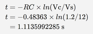
So, in theory, the relay would stay on for 1.1 seconds after the power supply is disconnected. Given everything else is a fixed value you can see that by altering the value of the capacitor we can increase or decrease the length of time that the relay is held on for.
So, we’ve now got the relay delay we were looking for however we need the capacitor to charge up as soon as possible when the user operates one of the front panel switches. The user isn’t going to want to hold it on for a few seconds while the capacitor charges … they’ll just want to give it a flick. You may have spotted that there’s no resistance between the capacitor and the power supply (or rather there is resistance in the connectors and wires and so on but it’s really really small). A very small resistance will result in a very small time constant and so as it stands the relay will charge pretty much instantly … but that presents us with a problem. By ohms law a circuit with a resistance of say 0.01 ohms at 12V will cause an initial current of 1200 amps! In reality we’d be dealing with an even smaller resistance and therefore an even higher current. That said though the power supply can only provide so much current but that greedy capacitor will consume as much as it can get. Why is that a problem then? Well, it’s not unusual to have larger capacitors wired directly over a power supply and these act to ‘smoothe out’ any dips in voltage but as explained above initially they’ll consume a lot of current whilst there is little resistance. The problem for us in the auxiliary controller is diodes. When the user flicks a primary switch on the front of the computer it’ll need to start the clock however we don’t want a signal coming in from one switch to back feed another as we’ll also be using the switches to know if it’s a long or short operation and also which operation to perform … diodes fix the problem nicely for us here. Throughout the computer I’ve been using 1N4148 signal diodes being as they’re cheap and work well for what I need but if you take a look at the data sheet you can see they can only withstand a maximum continuous forward current of 300mA … quite a bit less than the 2A that the capacitor could in theory draw. As it stands when the user flicks any of the primary switches the operation will run but that’s the last time it’ll ever run as the diode will have burnt out forming a permanent open circuit.
What’s the fix then? Well we need to bring down the current drawn by the capacitor to less than 300mA. If we build in a safety margin of say 50mA then by ohms law again we’ll need a 48 ohm resistor to limit current to 250mA. Now, resistors only come in standard values but it also depends what you have laying around and I’ve got a load of 220 ohm resistors for some reason so let’s try those … again via ohms law for 220 ohms at 12V we get 54.55 mA which is well within the diode limit. The updated relay circuit now looks like this:
Being as I’ve upped the resistance I’ve brought down the capacitance to 47 micro-farads to compensate a bit. So what does that do to the timings …
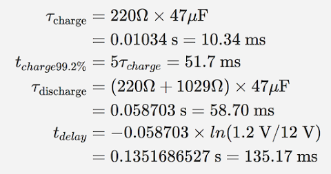
Firstly we have the charging time constant which is 10.34ms and therefore it’d take 51.7ms to get the capacitor up to 99.2% of the supply voltage. This is well within the time it takes to flick one of those primary switches so we’re all good there. For the discharge side we’ve now got the 220 ohm resistor as well as the internal resistance of the relay coil so we now have a discharge time constant of 58.7ms which means that it’d take 135.17ms to discharge from 12V down to 1.2V at which point the relay would turn off.
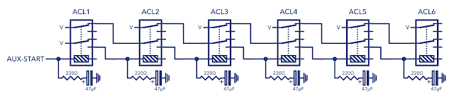
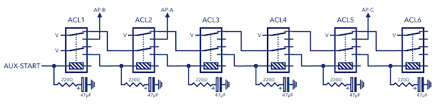
Right then, we’ve finally got a relay that will stay activated for a fixed duration of time following activation (and without destroying any upstream diodes). We can now string a chain of these relays together to form a ripple effect where each relay controls the next two relays in sequence. Here’s the updated schematic:
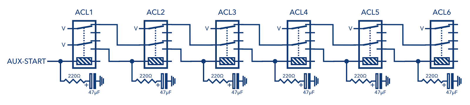
Hopefully you can see the pattern but if not here’s a table of the sequence:
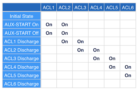
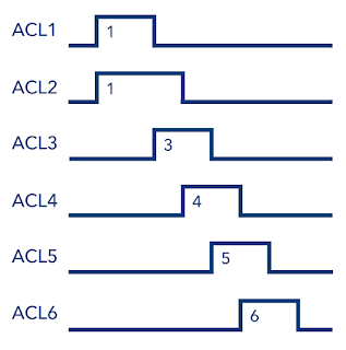
Which interestingly enough behaves a bit like the main sequencer in the computer (moving from one stage to another in sequence) but also behaves a bit like a clock (changes at a steady rate). Looking at the table another way we now have the following timing diagram:
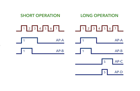
Let’s take a look at the operation pulses we’re aiming to derive and see if we can spot any clock pulses we can use:
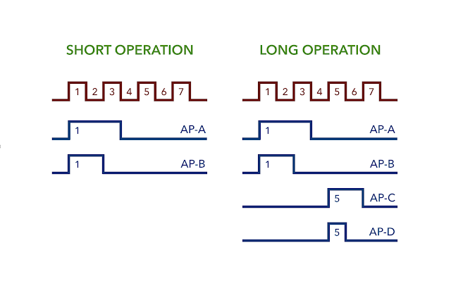
It looks like we’ve got a match straight away: AP-A = ACL2 and AP-B = ACL1. Looks like there’s also a match for AP-C on ACL5. I say all this like it’s a happy coincidence but of course it’s all planned in the design although it’s probably more correct to say that the control pulses are a consequence of the nature of how the clock works. Here’s the relay schematic with the pulses wired out:
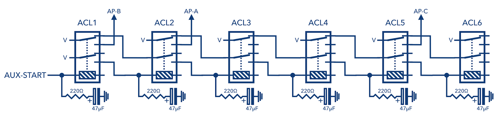
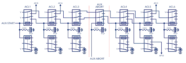
But what about AP-D though? There’s no obvious match for that pulse but what we could do is take AP-D when both ACL4 and ACL5 are active at the same time which will give a pulse lasting half the length of AP-C. There’s a bit of a problem with that though as I’m out of contacts on the relays … I need another set on ACL5. Come to think of it I’ll also want to have an LED showing the state of each relay for debugging purposes but I can’t connect this to the relay coil as the LED has an internal resistor which will change the delay timing so I’ll need a fresh set of contacts for that too. OK, it’s time to add more relays:
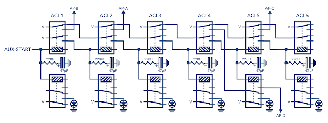
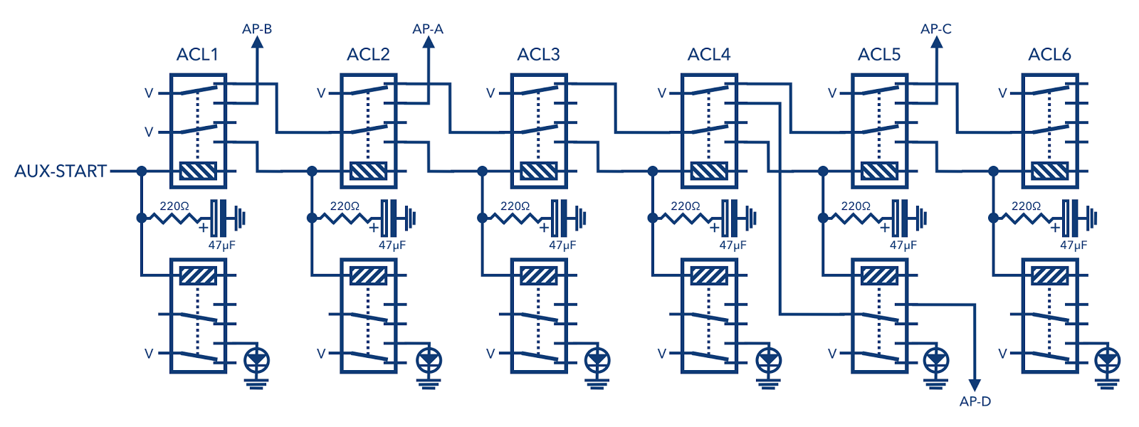
That’s all four pulses now accounted for so all that’s left is to find a way of making a short operation which stops after AP-A and AP-B to go alongside the long operation which carries on through to AP-C and AP-D. Ah, and I’ve inadvertantly introduced a change to the relay delay timing … can you see why (no prizes for guessing)? There’s now two relays / two coils / two sets of coil resistance on each clock stage. We’ll need to recalculate the timings accordingly taking special note that we’ve now got a 220 ohm resistor in series but then two 1029 ohm coils in parallel. Pocket calculators at the ready:
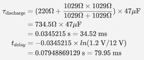
As we can see this brings the delay time down from 135.17ms to 79.95ms which makes sense as there’s now two discharge paths through each coil so the capacitor drains quicker than before. This also means that even if we found we only needed one relay and not two at any stage in this clock we’d need to put in a 1029 ohm resistor to ‘simulate’ the missing relay’s coil in order to keep the timing consistent at each stage. ACL6 is one such example where we could reduce down to one relay as we’re only using two sets of contacts.
Anyhoo, back to implementing the short operation. To make this work we need a way of disrupting the clock between ACL3 and ACL4. Let’s add that in now:
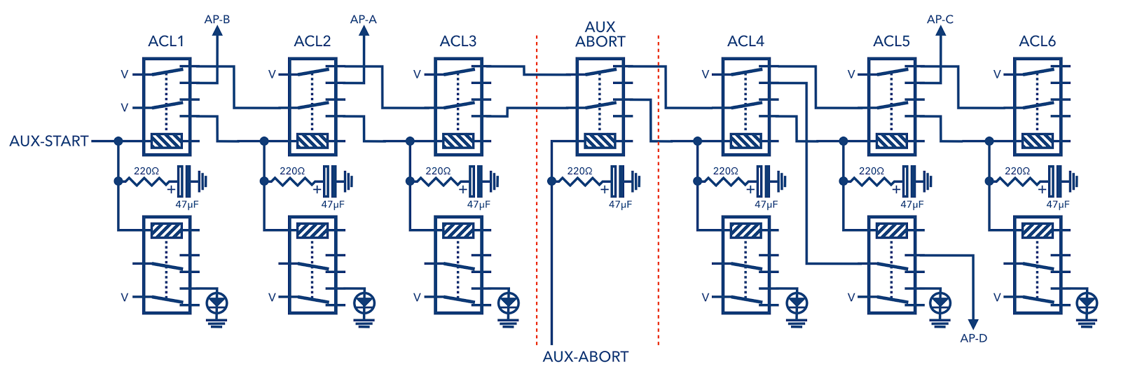
As long as the ‘AUX-ABORT’ line is held on then ACL3 is disconnected from ACL4 and the clock will die off when it reaches that point. I need to make one final tweak to this schematic though due to the way the AUX-ABORT line is activated … it’ll be driven when the user flicks any of the short operation switches which means it’s only on for a short time. I need to lock the line on once initially activated. I also therefore need to be able to release the line again once the sequence is finished. That’s done easy enough with few more relays:

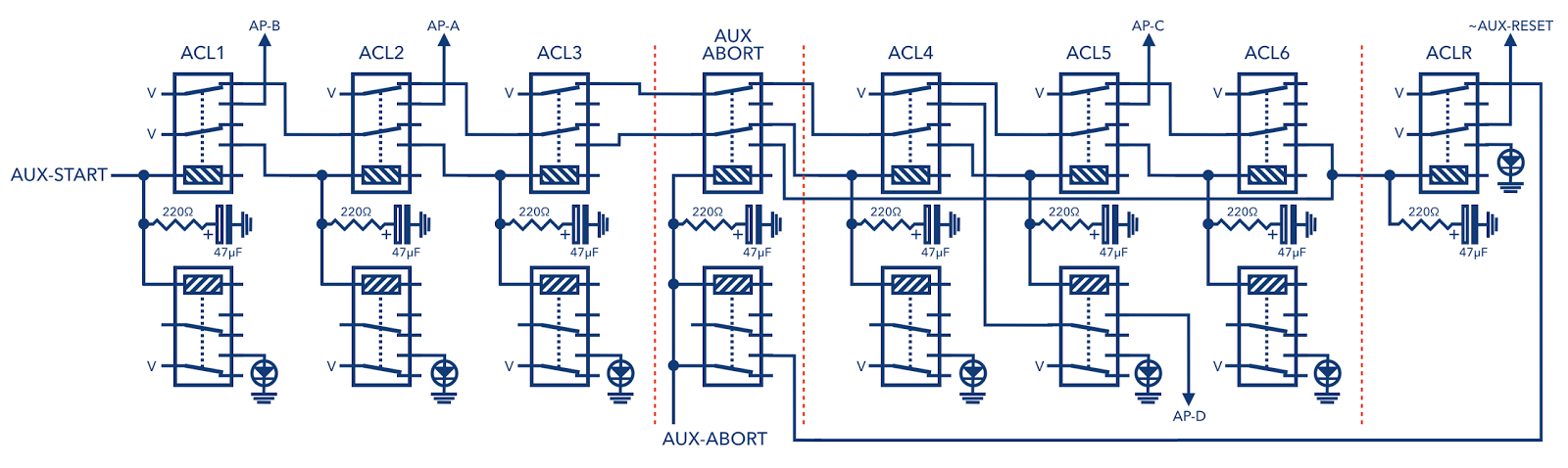
You’ll be pleased to know that at last we’ve reached the final schematic … if the image above is a bit small you should be able to click on it for a larger version. So, at ACLR we channel voltage out and back to the AUX-ABORT relays which will mean that once AUX-ABORT is activated it’ll connect itself to this supply and stick on until ACLR is activated at which point the supply is cut and AUX-ABORT turns off when the capacitor drains down. ACLR is activated by either ACL3 or ACL6 depending on what state AUX-ABORT is in. Finally we take an LED off ACLR when it’s active and the ‘~AUX-RESET’ line when it’s not. The control relays will make use of this ‘NOT AUX-RESET’ line as we’ll see in the third post of this series.
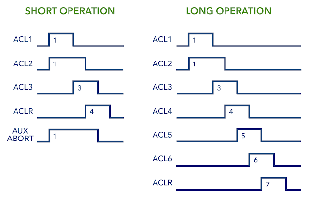
To wrap up then let’s update the timing diagrams one last time to show how the abort and reset stages affect the short and long operation timings:
Right, that was one mahoosive post and it’s taken ages to write but hopefully you can now see what’s behind the auxiliary clock. In the next post I’ll round off the auxiliary control design by putting together the groups of relays that operate the various control lines and I’ll put everything together from all three posts to produce the final auxiliary control board design.