My relay computer is now at the point where it can execute a program in memory without assistance. In order to do that though, of course, the program needs to be loaded into memory in the first place and at the moment that’s a bit of a pain. For each line of the program you need to set the primary data switches to match the desired ‘opcode’, gate the switches to the data bus, gate the program counter to the address bus, gate the data bus to the memory and then write to the memory - that’s four buttons to press simultaneously. Once that’s done the program counter needs advancing ready for the next line of the program via holding the select PC and load INC buttons followed by select INC and load PC. This cycle is repeated for each line of the program until it’s all loaded into memory. Like I said, it’s a pain and there must be a better way to do this.
Fortunately I don’t have to look too far for inspiration of how to simplify loading programs. Effectively I need to fire certain control lines in a certain order. Sound familiar? Well it should as it’s effectively at the heart of how the relay computer itself works - the controller unit does just that. So, what’s needed is a secondary controller that operates independently of the main computer which handles these specific operations - effectively an auxiliary controller. Below are the operations that would be useful and therefore the ones the auxiliary controller should implement:
- Load Address: Sets the the program counter from the value currently on the primary switches. Note though that it’s only possible to set the lower 8-bits of the PC … the upper 8-bits would always be zeroed out. This was an early design choice around having 16 switches solely for loading values to the address bus or sharing 8 switches between the data and address bus … I opted for the more compact option.
- Examine: Loads the instruction register from the value held in memory at the address pointed to by the program counter.
- Deposit: Loads the value currently on the primary switches into memory at the address pointed to by the program counter.
- Examine Next: As ‘Examine’ but advances the program counter afterwards. By repeatedly selecting this operation you could view a whole program to ensure it’s been entered correctly.
- Deposit Next: As ‘Deposit’ but advances the program counter afterwards. By repeatedly selecting this operation (and changing the value on the primary switches) you can load a whole program in to memory ready for execution.
The switches for these operations have actually been part of the computer for some time now but haven’t been used (or they’ve been directly wired to other control lines for ease of use at the time). As a reminder this is what they look like (across the centre of the picture):
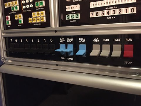
As you will hopefully have seen in one of my many videos on YouTube all of the blue and grey switches above are momentary and return to their positions pictured above. It’s the blue switches we’re concentrating on in this post and the first two can be pressed up or down to get the ’next’ and ’normal’ versions respectively of the ‘deposit’ and ’exam’ operations. That just leaves the third blue switch which is flicked up to run the ’load address’ operation. The switches are laid out so that the more common operations like loading a program are nearer physically to the black primary switches.
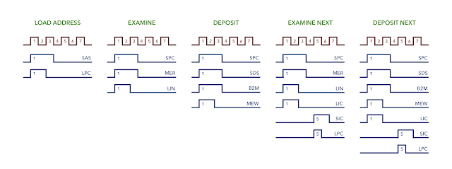
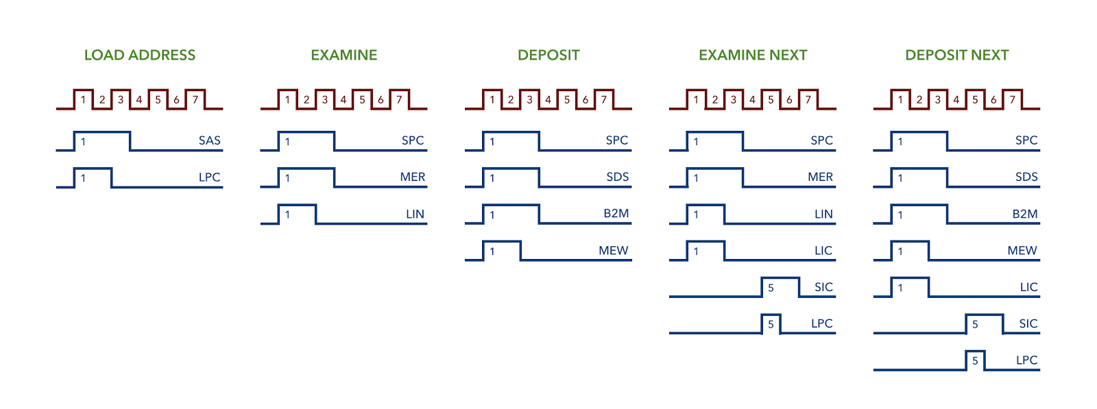
So, we have our switches laid out and we know what operations we want to perform. The next job is to decide what control lines we have to fire, and in what order, to implement each of the five desired operations. Well, on the whole, I’ve already been doing these operations by hand when operating the computer via the control line buttons in the top left of the picture above. Effectively I just need to draw out a timing diagram representing what I’ve been doing. Here that is:
The load address operation is quite simple: gate the switches to the address bus (SAS) and load the program counter (LPC). As always for the relay computer it’s necessary to stop loading the PC (or indeed any register) before taking the switches off the address bus to ensure the value latches in to the PCs register. The examine operation is roughly similar but selects the PC (SPC), reads the memory (MER) and then loads the instruction register (LIN) - ultimately just transferring a value from one place to another. Next up the deposit operation goes one step further and uses four control lines: select PC (SPC), gate switches to the data bus (SDS), gate the data bus to memory (B2M) and finally write to the memory (MEW).
The ’next’ operations mirror their examine/deposit equivalents but with incrementing the program counter bolted on. Firstly they hit the load incrementer (LIC) whilst doing their operation and this makes use of the fact that the PC is already selected (SPC). With this done the incrementer register is now holding the PC value plus one. To get that value back in to the PC we need to select the incrementer (SIC) and load the PC (LPC). This is done after the main operation ensuring the address bus is free and available.
The next step in designing the auxiliary controller is to look for patterns in the timing diagrams above and just as in the main controller we’re looking to define re-usable pulses. If you look closely you can see there’s four different and distinct pulses in use. Also of interest is that the first three operations only use two of those pulses whilst the ’next’ operations make use of all four. Effectively then we’re looking at the following:
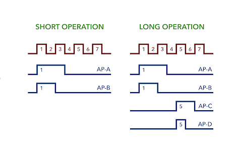
The four pulses are named AP-A, AP-B, AP-C and AP-D. AP in this case stands for ‘Auxiliary Pulse’ in order to differentiate them from the main controller’s pulses P-A, P-B, P-C and so on.
Now, in the computer itself the controller card receives its pulses from the sequencer which itself is then driven by the clock. It would probably therefore make sense to duplicate that set up here but we can actually simplify things a little and as it turns out we can actually take the pulses straight off what will become the auxiliary clock. That though is probably a subject in its own right and so I’ll pick up on the auxiliary clock in my next post.