In my last post I covered the construction of the lower incrementer card which is effectively a 16-bit half adder. This time I’m going to cover constructing the upper card of the incrementer which is a 16-bit register that can hold on to the incremented value before pushing it back out to the address bus.
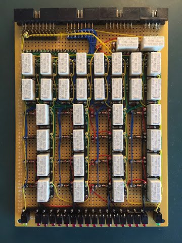
The backplane connectors and LEDs were soldered down in my last post but there’s plenty more soldering to do. First up I can add the relay sockets, wire wrap posts and card interconnect wrap posts:
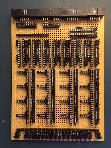
This time around I haven’t soldered on the stacking header that connects the two cards together just yet as I’ve found it gets in the way when wire wrapping or can be damaged if I’m not careful. I’ll solder this on just before I bring the two cards together to form the incrementer unit as a whole.
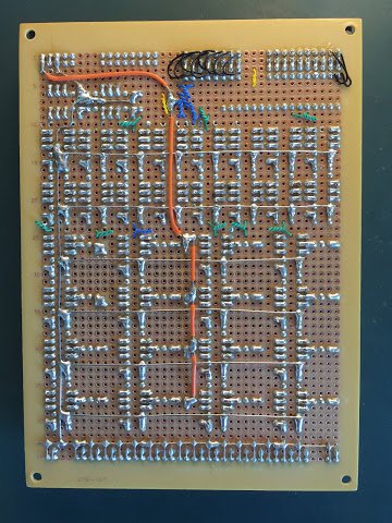
Next up I can solder down the ground and power rails on the back of the card:
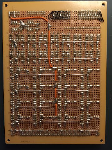
Nothing too unusual here besides there being quite a lot of relays on this card and consequently a lot of ground rails. So, soldering done (for now) … on to the wire wrap …
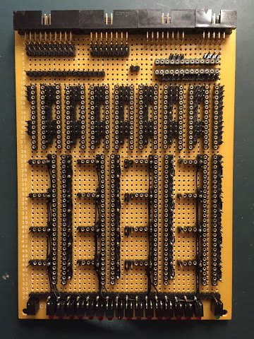
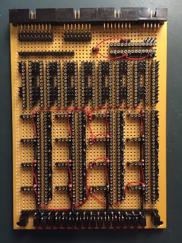
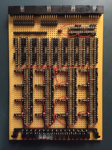
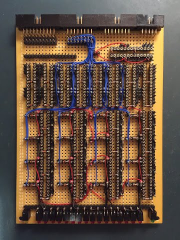
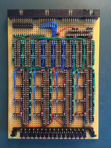
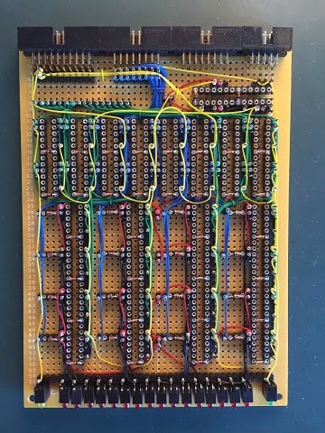
Going through the pictures in order (top left to bottom right) we have: the internal register relay bits wiring; the power supply wiring; diodes added; the outbound address bus wiring via the gating relays; the inbound incremented value wiring (again, via gating relays) and finally the control wiring.
With the wire wrap done the card is pretty much complete - just needs the relays popping in …
… and that’s it for the upper incrementer card. You might have noticed that this post has perhaps been a little brief and that’s because there’s not much to show that hasn’t been seen elsewhere before. Partly that’s because this is effectively just another register but also because I’m pretty settled on the construction method I’m using. One slight slip up on this card though is the use of diodes on the outbound address bus coming off the register bit relays. They’re not actually necessary as there’s no risk of backfeed messing up the register’s value and it’s come about because I’ve copy/pasted the design from another register and tweaked accordingly. In practice it won’t cause a problem just meant the card was slightly more complex than it needed to be.
In my next post I’ll sandwich the upper and lower cards together and then give the whole incrementer unit a test.