We’re getting nearer and nearer to a computer that can run though a program in memory rather than just a single instruction … we’ve got memory to hold the program and a program counter to point to the current instruction in memory. Now it’s time to construct the 16-bit incrementer which will be used to advance the program counter on to point at the next instruction.
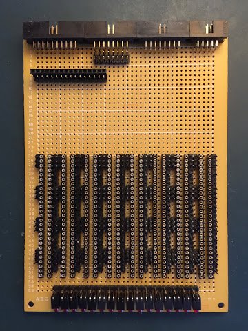
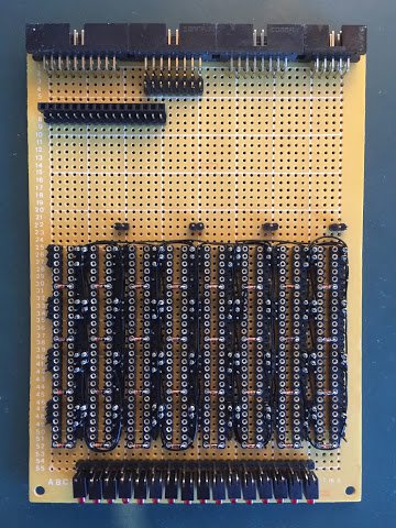
As the incrementer is spread over two cards I’ll likewise spread the construction over two blog posts focussing this time on the lower card. Before that though I’ll get a head start and solder down the LEDs and backplane connectors for both cards:
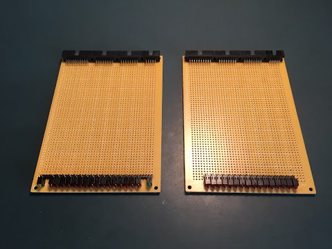
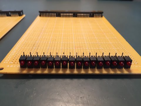
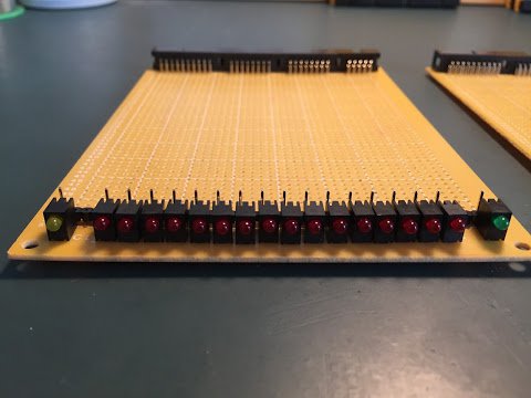
For the lower card there are 16 red LEDs which show whatever value is currently on the address bus plus one (and if nothing is on the address bus then it’ll show a value of one). The upper card likewise has 16 red LEDs flanked by a yellow LED on the left and a green LED on the right. This is the register part of the incrementer so what these LEDs show is the current held 16-bit value with the yellow LED lit when loading and the green LED lit when reading back out to the address bus.
Right, I’ll leave the upper card there and pick it up again in my next post. Let’s focus on the lower card …
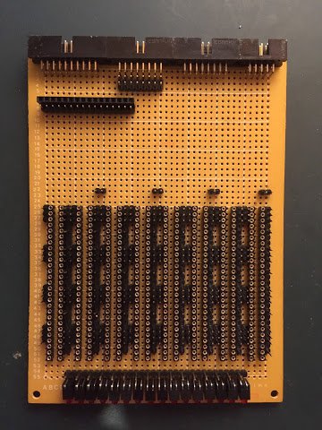
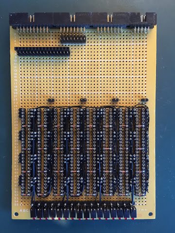
In the picture above I’ve soldered down all the relay sockets (using the same long column pattern I used on the upper memory card) along with the wire wrap posts. There’s also the card interconnects at the top left which take the output from the 16-bit adder off to the upper card’s register so the value can be held and then pushed out to the address bus. This card will also need some wire wrap posts connected to 12V so I’ll add those next:
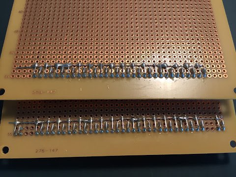
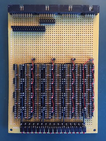
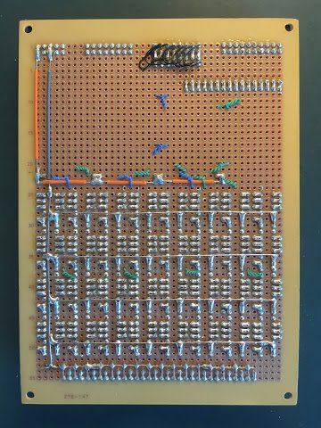
… and viewed from the solder side of the card it now looks like this …
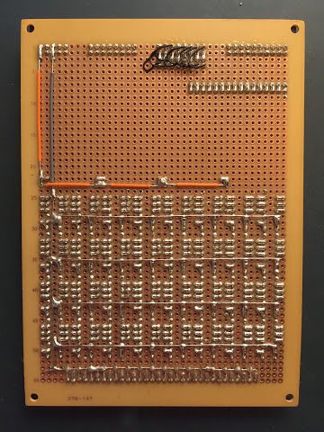
As with other recent cards all the vast majority of ground lines are straight lengths of bare wire (which speeds up construction) whilst power lines are insulated wire. The only exception here is the last part of the ground wire which is insulated. There’s a reasonable amount of spare space on this card which could be utilised in the future if needed (and if I have something that needs the same backplane connector set).
Right, soldering done. Let’s pop the diodes in and get the card wire wrapped:
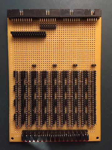
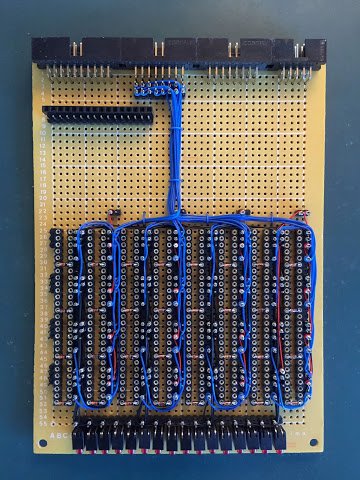
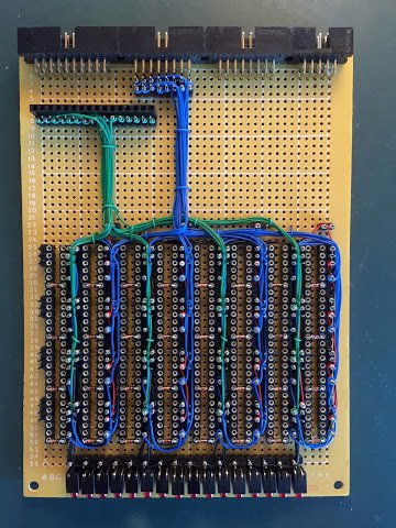
Working through the images in order we have: diodes inserted; internal adder wiring; LED wiring; power wiring; incoming address bus wiring and finally outgoing incremented value wiring. As usual I’ve bundled wires together with a wire clip to keep everything neat and tidy.
With all the wiring complete the last job is to pop the relays in and the lower incrementer card is complete:
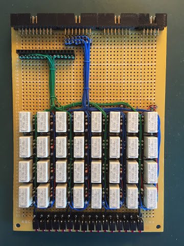
Due to the way the card is designed it’s possible to test the lower card in isolation of anything else and I’ll show that in the usual video when I’ve completed the incrementer as a whole (sorry for the tease but those videos take ages to put together ;)
In my next post I’ll construct the upper incrementer card which is effectively just a register … or as I’m beginning to refer to them … YARs … yet another register.