Continuing on with the theme from my last post … here is another ‘miscellany special’ covering all the little ‘side jobs’ I’ve been doing on my relay computer alongside the primary work of constructing the Program Counter, Memory and Incrementer cards. There’s three things worth covering (plus an additional minor mention) … let’s start with backplanes.
The computer is designed with four backplanes (W, X, Y and Z) each taking five cards. Each card of the computer is designed to fit in a specific backplane as each backplane offers a unique selection of busses and connections. Generally you can put a card designated for a given backplane in to any of the five backplane slots (position mainly being an aesthetic thing) however the W backplane is the notable exception having slots W1 - W2 - W1 - W2 - W1 taking two double cards (with W1 and W2 connectors) and one single card (W1 connectors).
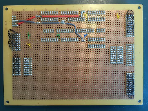
Anyhoo, the computer might well be designed to have four backplanes but currently it’s only got two constructed (W and Z). The instruction register card is type X but as it’s on its own at the moment the busses are plugged directly in to the card. This soon becomes unworkable however when the Program Counter and Incremeter are built as they are also type X cards … plus the Incrementer is built over two cards so we’re looking at an additional three type X cards. Time to build another backplane:
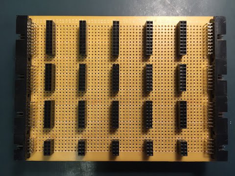
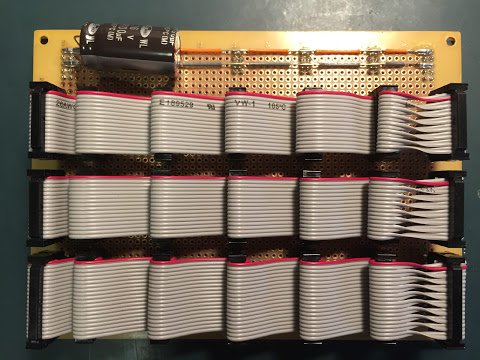
There’s nothing particularly unusual about this backplane compared to the two already constructed although those of you out there with a good eye for detail (for whom my work must eternally frustrate) will notice this backplane has a dirty great capacitor stuck across the power rails. This is something that should have been on the other backplanes (and will be added later) to smooth out the power supply. With so many relays switching on and off there is a danger of the power supply getting really noisy which the relays themselves can likely tolerate but the memory chip or similar wouldn’t be pleased at all. In this case ‘dirty great’ is defined as 4700uF. Given there’ll be four of these it’ll have a slightly odd effect on the computer when turning it off at the mains … the computer will keep going for a couple of seconds as it drains the reserve in the capacitors then when the voltage dips below the relay release limit any relays that are on will start dropping out. It’s an interesting effect and you’ll be able to see it in my next demo video.
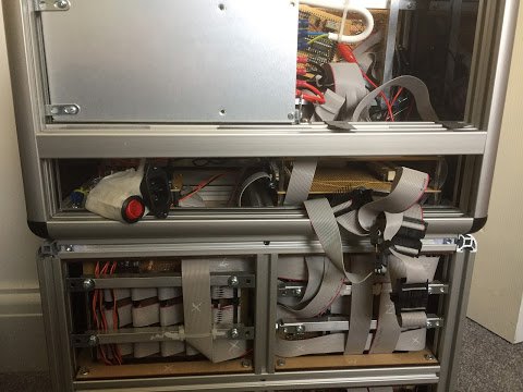
These backplanes are fairly repetitive to build and fortunately there’s only one more to go after this one … the Y backplane. Unfortunately the Memory cards are type ‘Y’ … and yep, that’s cards plural again as the Memory unit is spread over two cards … so it won’t be long before I’ll be building the fourth and final backplane. If for any reason I did have to rebuild any of these backplanes I think this is the point where I’d switch to etching PCBs … something I considered for the cards of the computer in general rather than wire wrap. It’d certainly be quicker but is harder to change if there’s a design fault somewhere. The worry with the backplane is that there’s lots of connecting parts so there’s many more places faults could happen and I have had issues in the past with the ribbon cable sockets not making a sound electrical connection with the sockets on the board. Anyway, musing aside, here’s how the backplanes look in the computer viewed from the front:
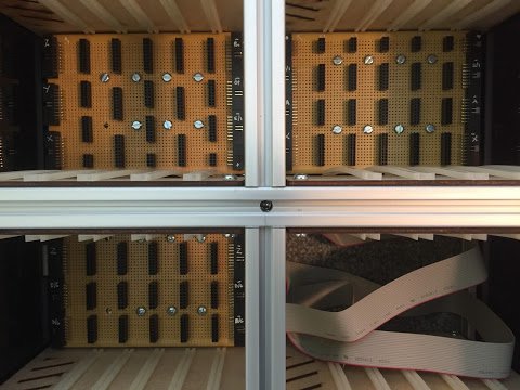
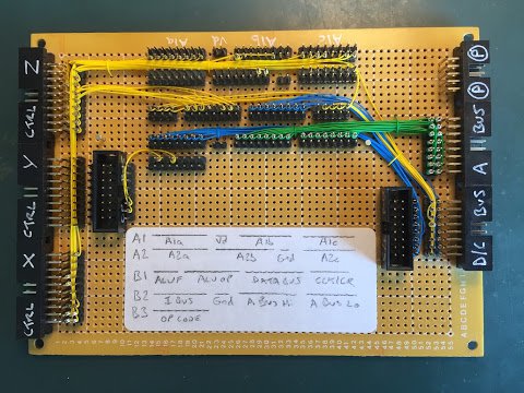
If you click the picture for the slightly larger version you can see I’ve had my little white pen out again and I’ve marked up the connectors at the left and right of the backplanes to make it easier when identifying which ribbon cables go where. Speaking of which, that brings me nicely on to the second subject - ribbon cable routing.
With the three backplanes in place I’m now at the point where everything that’ll need the X and Z control busses exists and is sat in its final resting place in the computer. If you’ve seen my last overview video you’d have noticed that generally the cables running through the back of the computer can only really be described as ‘an awful mess’. It’s time to do something about that:
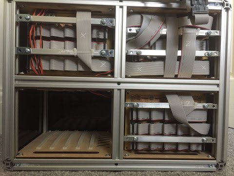
For the X and Z busses I’ve neatly routed, folded and labeled the cables and also put some cable tie restraints together to keep them in place. I’ll continue this way of routing the cables as busses become more permanent. Note therefore that in the case of the D/C bus (which comes off the Z backplane at the bottom right) it loosely weaves its way up past the W backplane … eventually this will be nicely routed and labeled.
The three control busses (X, Y and Z) all head up to the upper enclosure via the left hand slot. It’s quite hard to see in the picture but the Z bus goes up behind the X cable having visited the W backplane on its journey from the Z backplane. When the Y backplane is added the Y control bus will similarly visit the W backplane on it’s journey to the upper enclosure and also leave via the left hand slot. The D/C, C/I and D/I busses go up to the upper enclosure via the right hand slot. Again, as these aren’t permanently routed at the moment it’s a bit messy. Speaking of which, there’s the usual mess of connectors in the upper display for the D/C/I busses:
The mess of cables and connectors is due to needing to connect the C’s, D’s and I’s together of the D/C, C/I and D/I busses. All three busses come up from the lower enclosure but only two go off to the upper enclosure cards (D/C and C/I). Later on I’ll create a small ‘break out card’ where each bus can plug in to and each line of each bus will be wired out. This should massively neaten things up in this area. Eventually there’ll be another perspex/acrylic panel where the cables are currently spilling out and not only will this be where the mains cable will plug in but also all of those busses that have come in to the upper enclosure will also be exposed via sockets so that it’s possible to plug in extensions and add-ons to the computer.
While we’re in the upper enclosure I’ll quickly cover some minor fittings/fixtures changes:
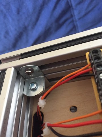
As the computer is getting heavier and heavier I’ve decided to securely fasten the upper enclosure to the lower. Originally I wanted to have it so that the two halves could be split to make carrying around easier but it really complicated the busses as I’d have to have some quick way of disconnecting them. In the end I just gave up and bolted the two halves together. There’s four of these brackets, one in each corner, and they’re very strong but also electrically conductive which means the whole case goes back to the power supply earth just in case something nasty were to happen. Whilst I was fixing things to other things I also put some brackets in to sit the upper cards on. These were previously floating around inside the case so this is a much better alternative. The cards are only secured at one side due to the holes in the right hand brackets not quite lining up. Gravity works in my favour on this one so the brackets are effectively just taking some of the weight.
Right, last subject … the address bus. With the new type ‘X’ cards I’ll be creating it’s now time to implement the address bus. As far as the backplanes are concerned that’s an easy one - just a 16 way ribbon cable - but it’s at the upper enclosure where a little more work is required. Firstly I need to be able to gate the front primary switches to the address bus. That’s just a hand full of relays and a new Sel-AS button so that the front panel now looks like this:
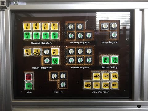
Whilst I was at it I also soldered down all the remaining switches (to avoid repeatedly taking the display A card out of the enclosure) and popped on the ld-PC and sel-PC caps which will be used for the upcoming Program Counter. Next up, I needed to add a display for the value on the address bus:
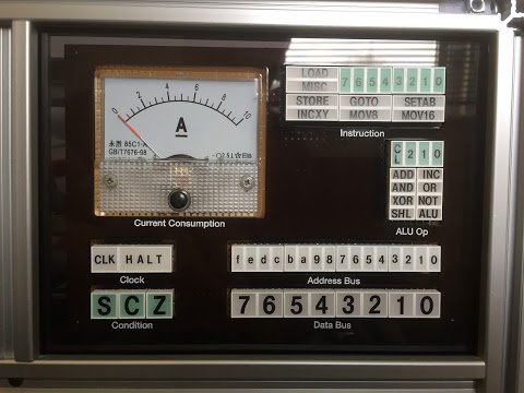
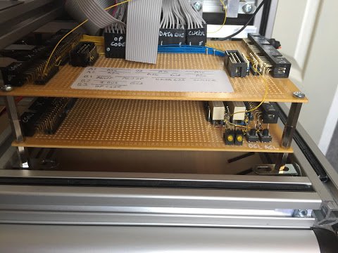
Here I’ve added the 16 LED bars to show the address bus contents just above the data bus display. Again, to avoid taking the card in and out of the enclosure, I’ve added all remaining display units. Effectively that completes Display B so what you see above is the final version of that card. Last job for the address bus is to wire it out on the display distribution card:
Nothing too unusual here - just more of the same - although one thing of note is that I’ve started making little cable ties out of Kynar wire to bunch groups of wires together. I quite like the way this looks so expect to see them more often in future cards.
Right then, that’s enough for this post and for my duo of ‘miscellany specials’. The next post will, finally, get on with the job of constructing the Program Counter and giving it a test (both on its own and inside the computer as a whole). After that there’s the Memory and Incrementers cards and then we’re getting close to having a computer that can run a simple program.