Having somehow forgotten to take time off work I’m now playing ‘annual leave catch up’ which means lots of four day weeks but also, and more importantly for this blog, I’m getting time to crack on with construction of my relay computer. The current milestone I’m working towards is finishing off the Program Counter, Incrementer and Memory cards (which are all well under way now) so that I can load a simple program in to the computer and set it running without any further intervention.
Now, if there’s one weak spot I possess (one of many I’m sure) it’s a short attention span. There’s a certain amount of repetitiveness in wire wrapping ‘register based’ cards like the Program Counter and Incrementer so it’s always tempting to indulge in a little variety and pick off all those ’little jobs’ that need doing on the computer. This post (and the one coming after it) sweeps up all those little changes that have been happening lately and attempts to record them before they get forgotten.
First up, lets talk about power. So far I’ve been running the computer off my bench power supply but the intention was always that the computer would eventually have a power supply of its very own. I did, momentarily, consider building my own power supply but decided I didn’t want my house burning down so I opted for an off the shelf job. A quick browse of Amazon led to a knock at my door the following day with a parcel containing this. Here’s some pictures of said power supply fitted to the computer:
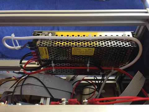
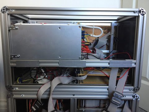
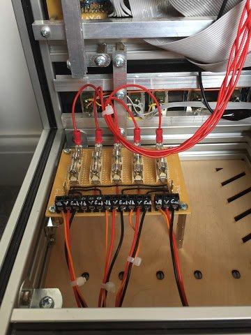
There’s plenty of choice with power supplies but I needed something that was going to fit in the computer case, run at 12V but also supply enough current. Enough current? Working out how much is enough has involved a fair bit of guesswork, fortune telling but mainly basic arithmetic. The power is distributed to the four backplanes plus display through five 2A fuses. This gives the power supply some additional short/overload protection but also limits how much current goes through the power wiring. All power cables from the fuses onwards are rated above 2A but of course the power doesn’t stop there - it goes in to any number of relays and then fans out from there. Example calculations coming up next but let’s take another quick picture break … here’s the power distribution board with those 2A fuses:
So, let’s take an example. Looking at the relay data sheet the coil in each individual relay has a resistance of 1029 ohms so when pushing 12V it should consume 0.01166180758 amps (via ohms law of I = V / R) which is 11.66mA. Using the power triangle where P = I x V the coil should therefore use 0.139941691 watts of power when energised which is 139.94mW which is pretty much the 140mW stated in the data sheet. Let’s look at one of the ‘hungrier’ cards - the Program Counter. This card is effectively a 16bit register so in a case where all bits are set that’s 16 relays on at the same time for a total of 199mA. The card doesn’t just consist of relays though … there’s the LEDs to consider too. Each LED consumes around 10mA so that’s another 160mA to the pile giving a running total of 359mA which is 0.36A.
OK, so let’s assume each backplane has five of these ‘hungry’ cards mentioned above. That’d give us a total of 1.8A per backplane which is still comfortably within the 2A limit the fuses impose. In practice I’ve rarely seen the consumption for the whole computer as it stands go above 2A but it’s something I’ll need to always keep an eye on … or at the very least the fuses will tell me if we’ve got too greedy for power. The power per backplane can, of course, be calculated if you follow every route the power goes but let’s not … let’s assume 2A should be enough.
So, with five power lines taking up to 2A each we’re assuming a potential 10A total. Power wise that’s 120W … slightly more than those 100W light bulbs that you can’t buy any more. That doesn’t sound all that bad until you look at it another way … if you took a modern LED GU10 bulb at, say, 4W you could run 30 of them (perhaps two houses worth) or you could run my computer at full pelt (assuming it’d ever get anywhere near 10A of course). Let’s assume it will hit 10A … I now need to get that much electricity from the power supply to the distribution board … enter the power loom:
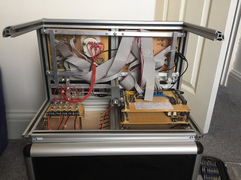
The wire I’m using for power distribution is stranded 16/0.2mm which is rated at 3A therefore can comfortably handle the maximum 2A that’ll go through each fuse. To supply the fuses I’ve used five lengths of this wire and then grouped them all together at the ammeter. The meter itself reads up to 10A so should be happy having that much flowing through it (you’d hope). The final part then is to wire up to the outputs of the power supply. There are two outputs each capable of delivering half the total 15A so using 55/0.1mm ‘flexi’ cables which are happy to carry 6A then we’ve split the 10A over two of these cables for a potential 5A per cable. With this arrangement everything has a little extra ‘wiggle room’ and is comfortably within tolerances. Here’s a close up of the ammeter with the incoming power lines and the wiring loom heading off to the distribution board:
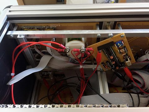
Looking at the picture above there’s an additional card (hanging at a jaunty angle) that you might not have seen before. This is the auxiliary clock which outputs a timing signal at varying frequencies. This replaces the temporary 555 timer I had on a breadboard but it’s worthy of its very own blog post so I’ll cover that in an upcoming episode. Speaking of which, lets leave this post there for now but in my next post I’ll continue sweeping up some of the miscellany before getting back on to the main job of constructing cards.