In the last post I introduced the design for the 1-bit Half Adder. This post covers connecting sixteen of these units together to make the 16-bit Half Adder.
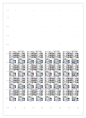
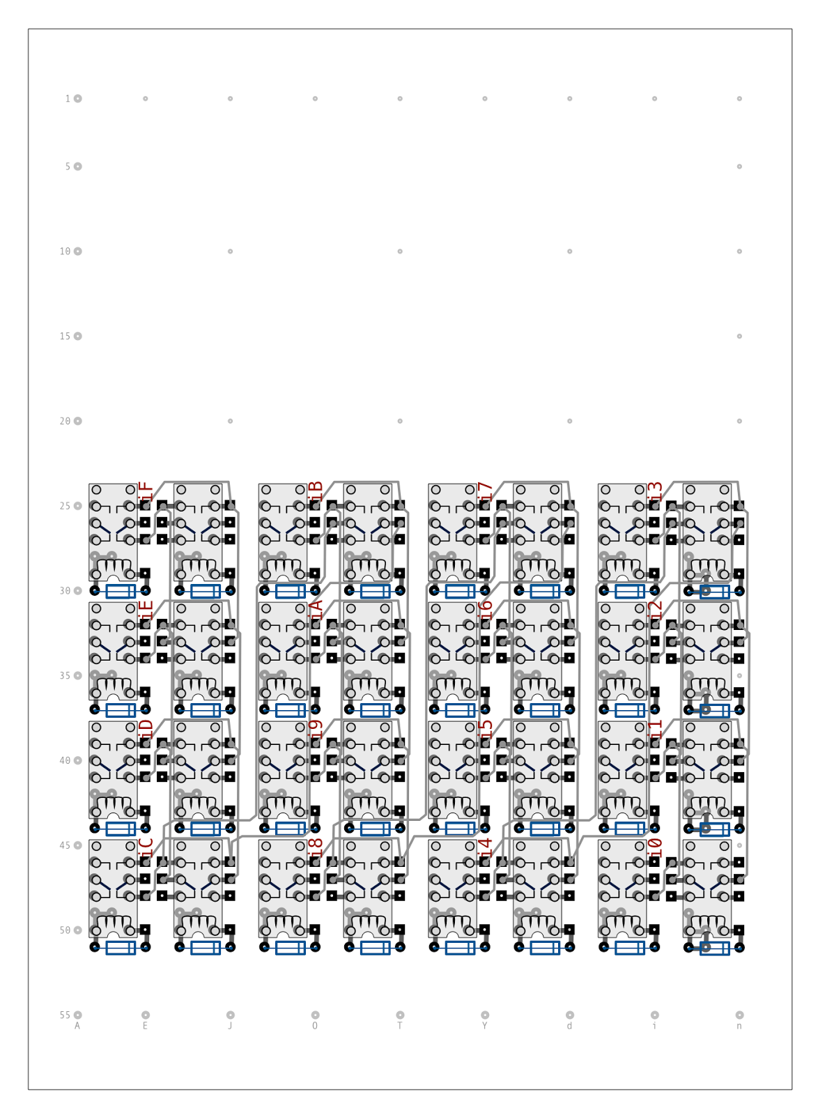
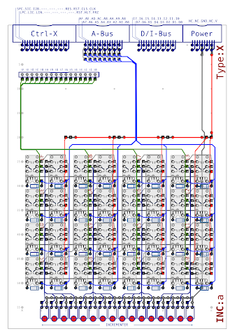
So, diving straight in, here is what sixteen of the 1-bit Half Adder units look like all together on the usual 55 x 40 hole pad board:
Each half adder bit is made up of two relays (as seen in the previous blog post) and starting at the bottom right of the diagram above the bit stages run upwards from 0 to 3 and then continuing on in rising columns to the left until bit 15 at the top left. Between each bit the carry out lines of the prior bit are connected to the carry in and the carry out lines connect to the carry in of the next bit effectively chaining each bit together to form a ripple carry adder circuit.
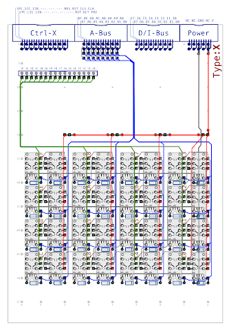
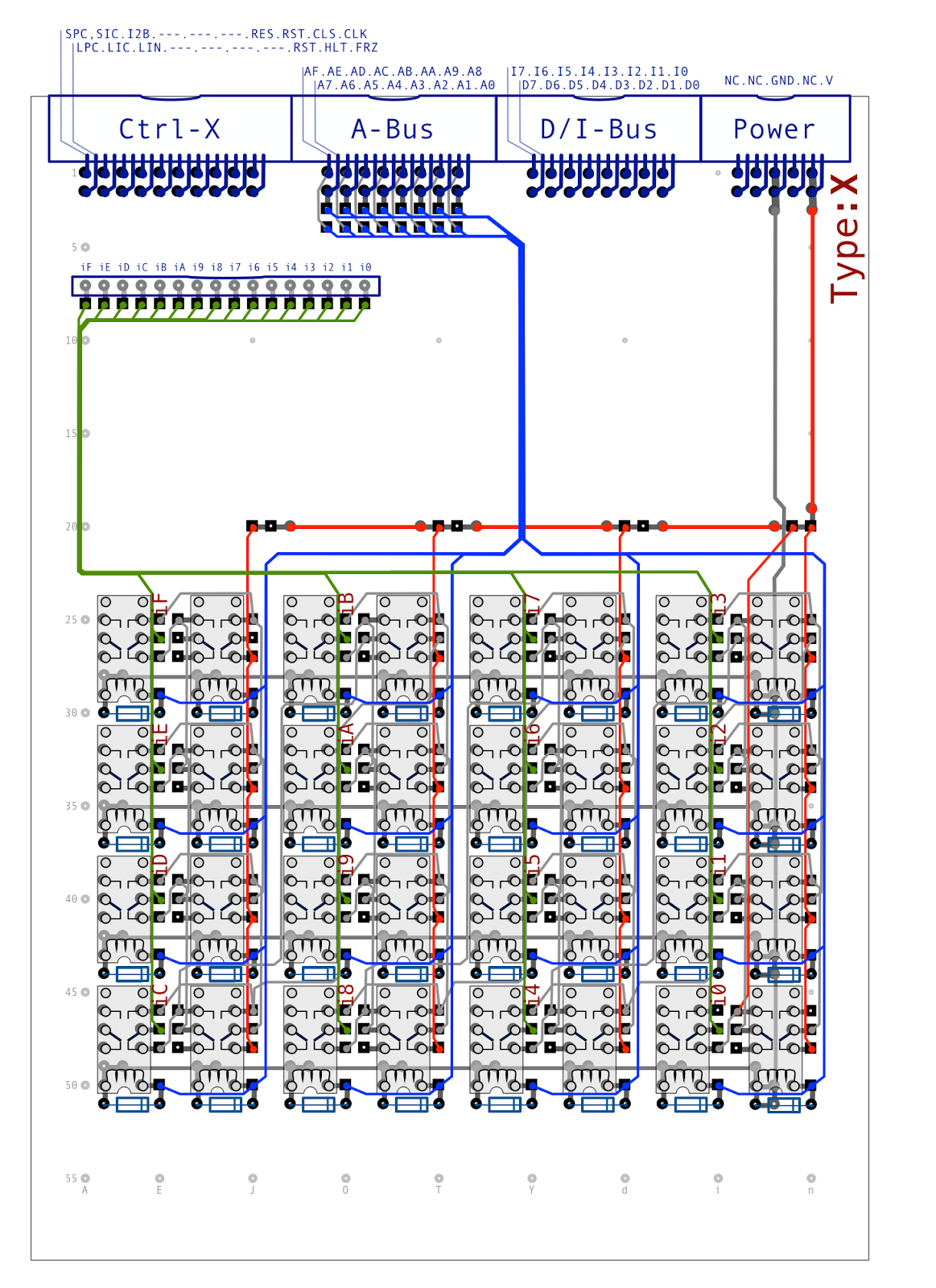
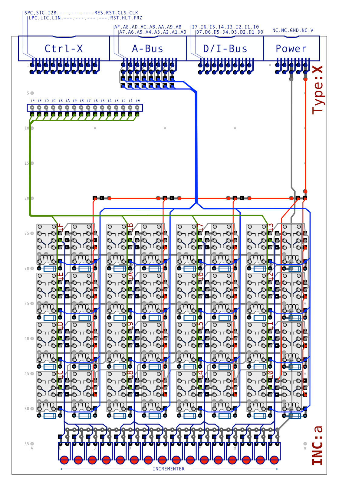
We can now connect up the inputs and outputs of the 16-bit half adder as follows:
Each bit of the half adder is directly connected to the address bus meaning that the adder is always active even when the output isn’t needed. As we want to increment the address bus value we also need to set the carry in signal of the first half adder bit. This line is therefore permanently tied off to the power supply. The output (the incremented address bus) is taken to an inter-board connector … more on this later. We ignore the carry out of bit 15 meaning that if all bits of the address bus are set the result of the increment will be all bits off.
As with other cards in the computer it’s always useful to observe the value a card is producing … and you can never have too many LEDs of course … so the final step is to add a row of LEDs across the front of the card:
With this design we can now take a value on the address bus and increment it by one. This is only half the story though as to be useful we need to store this incremented value in a register so that we can place it back on the address bus when needed. The incrementer unit has a built in register and that’s what I’ll cover in the next post.