It’s been a while since my last post … pretty much 10 months in fact … and I’d love to say I’ve been quietly working on my relay computer in the meantime but I haven’t. Designing, building and blogging about the various parts of the computer is really time consuming and unfortunately I’m just one of those people who has way too many hobbies. Anyway, after picking up some subscribers on YouTube I thought it was high time (or maybe I felt guilty enough) to focus back on the computer and get it through to the next milestone … where it can step through a simple program stored in its memory without any human intervention (beyond entering the program itself and setting the computer running).
So where to begin? The three units that’ll need building are the program counter, incrementer and memory. To recap: the memory holds the instructions that make up the program to be executed; the program counter points to the current instruction (line of program) in the memory; and the incrementer adds one to the program counter to move it on to the next instruction. Using those three units you can step through the program in memory and for each instruction load it in to the instruction register, move the program counter on and then execute that given instruction. The cycle is repeated until the end of the program is reached.
I’m going to start with the easiest of the three units described above … the program counter. Essentially this is just another register card similar the A/D and B/C registers created so far. The first difference is that the two 8-bit registers on the card are combined to make a single 16-bit register (bits 0-7 in the first register and bits 8-15 in the second). The second difference is that whereas the registers created so far can be loaded and selected on the 8-bit data bus the program counter is loaded and selected on to the new 16-bit address bus. The address bus is generally used to control which slot in the memory is required but later on there’ll be some other 16-bit registers which can pass values around on the address bus and be used for handling things like jumps within a program (for loops and branching based on the ALU condition register) and for storing and loading values in memory outside of the program code itself.
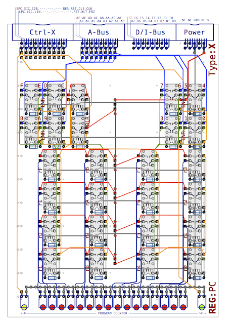
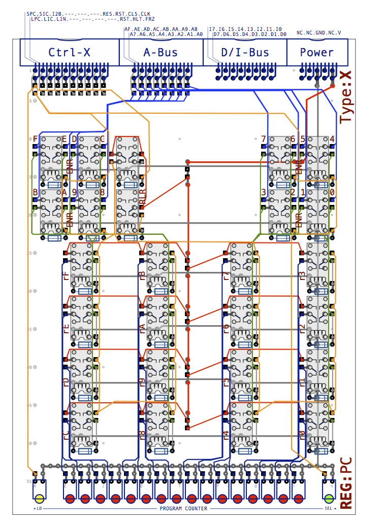
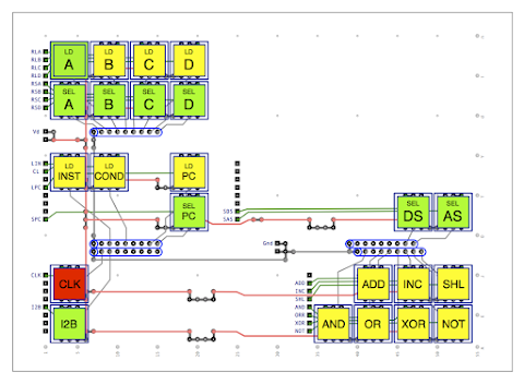
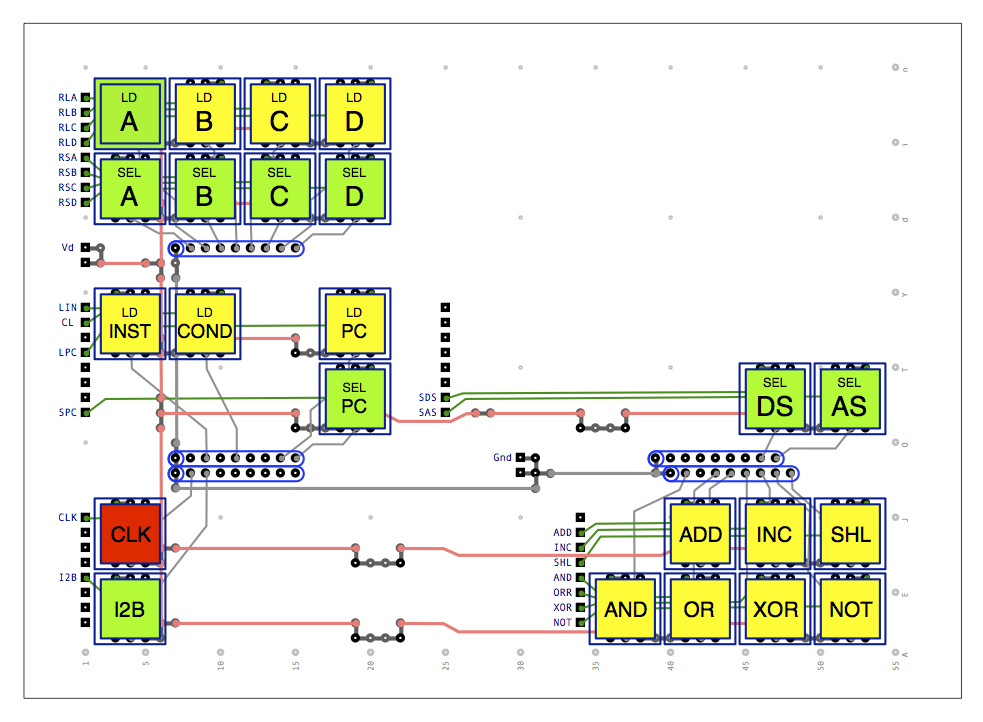
Given the program counter is very similar to the other 8-bit registers the schematic doesn’t need much introduction:
This is a type ‘X’ card (like the instruction register) and so has the same connectors along the back of the card (X control bus, address bus, data/instruction bus and power connector). Comparing it with the A/D register the main bit register relays are the same but notice that towards the top of the card there’s only one set of load/select registers and that’s because both 8-bit registers are loaded/selected at the same time. This is also shown down in the LEDs across the front of the card … there’s one load LED at the left, one select LED at the right and then the 16 LEDs in the middle showing the current 16-bit value held in the program counter register as a whole. You can click on the image for a closer look but if you want to get in really close you can find a version here in PDF format.
Whilst I’m creating the program counter it makes sense to update the two display cards and auxiliary control card so that the program counter can be accessed and observed when the computer is being operated manually. Let’s start with display B on which I’ll add the address bus:
The address bus consists of red LED light bars similar to the data bus ones but with each element half the width to fit the full 16 bits in. As with the program counter you can find a PDF version of the Display B card here and another version showing the LED internals here. Next up is display A which gains two extra control switches:
Looking towards the centre of the diagram above you can see the new load and select control switches for the program counter (LD PC and SEL PC). These allow the user to manually load or select the program counter from/to the address bus when required. Again you can find a PDF version of this diagram here and one without the switch caps here.
One thing to note in the diagram above is the ‘SEL AS’ switch which was previously wired up to the Load Condition Register line (before the LD COND switch was added). This now gets to take on its true purpose which is to gate the primary switches on to the address bus (in a similar way to how ‘SEL DS’ gates the same primary switches on to the data bus). You may have noticed that gives us a small problem as the primary switches allow the user to enter an 8-bit value but the address bus holds, of course, a 16-bit value. Consequently the ‘SEL AS’ switch will only gate to the lower 8-bits of the address bus. There’ll be a work around for this later where you could load the upcoming M1 and M2 registers one at a time which combine to make a full 16-bit M register which can then be selected on to the address bus. Typically the primary switches are used to load the PC with a starting address for a program and this will usually be in the first half of the memory (and even more usually will start at the first memory location so that just clearing the PC will give you the right starting address). The gating relays for the ‘SEL AS’ functionality can be found on the auxiliary control card. The design for this has been done previously and the PDF version of that can be found here.
Right, so that’s pretty much all the design complete for the program counter. The only other thing worth noting is that I’ll need to create a type ‘X’ backplane as I’ll now have two X cards (the program counter and instruction register). This is very similar in design to the ‘Z’ backplane so not really worthy of any further detail.
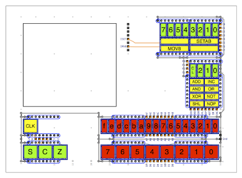
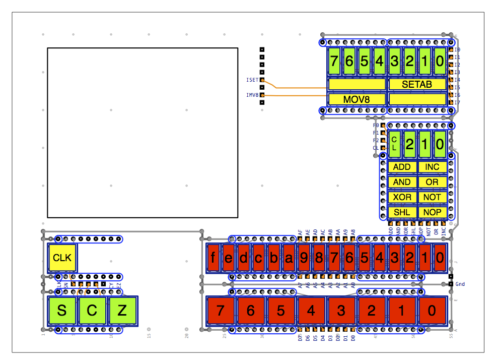
Finally to wrap up this post I’ve updated my relay computer simulator which now looks like this:
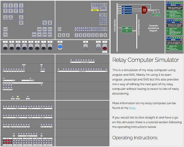
The latest version of this can be found here (although note that I only ever host the latest version so as this post gets older the simulator might be newer than you’d expect). Feel free to fire this up and have a play with the program counter. If you’re interested in what’s behind the simulator you can see all the source code on my GitHub page.
Next time I’ll cover the design of the incrementer which allows you to add one to the value of the program counter effectively moving it on to the next position in memory.