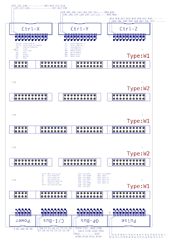
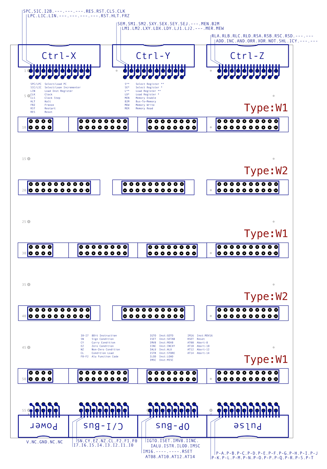
Before I can test the new decoder, sequencer and controller cards all working together with the rest of the computer I need to construct the ‘W’ backplane which the new cards sit on. Generally this backplane is similar in design to the ‘Z’ backplane that the ALU cards and A/D and B/C register cards sit on. However, whereas each card on the Z backplane has the exact same connectors the W backplane is slightly more complex as the sequencer and control units are spread over two cards each requiring a different set of connectors. The upshot is that the backplane has three ‘W1’ card slots and two ‘W2’ card slots. A diagram explains it better:
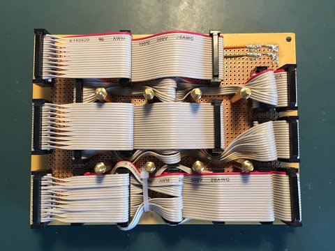
On the Z backplane each individual connector is joined to it’s siblings via a ribbon cable that runs the length of the backplane. The only oddity is that at the bottom of the backplane each pair of wires in the ribbon cable need twisting so that each line comes out in the right place. As you can see from the diagram above the W backplane is a bit more of a challenge. I’m still using ribbon cables to join the connectors together however this time the cables need to weave in and out to fit around the other connectors which are in the way. After much coaxing of wires I ended up with the following:
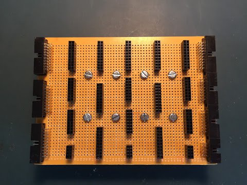
… and when viewed from the front the backplane looks like this:
… and that’s about it for the backplane although behind the scenes constructing the backplane is of course very time consuming and fiddly and takes careful testing to make sure all lines are connected OK. Fortunately the computer only has two other backplanes (X and Y) and those are very similar to the Z backplane so should be a bit easier to put together.
As the computer is gaining ever more cards I also wanted to start work on putting something more permanent together for distributing the power to each of the backplanes and display cards. Here is the power distribution board I’ve put together:
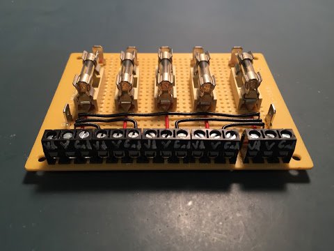
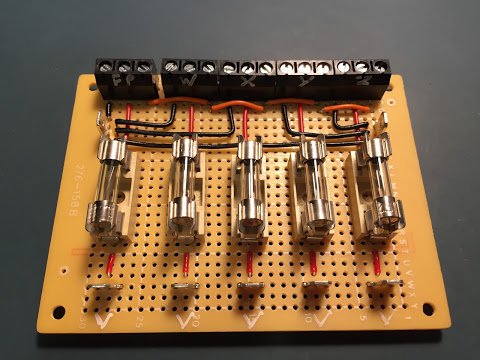
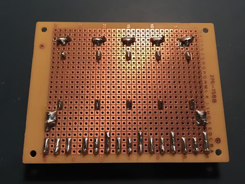
The board has five independent channels each fed from a metal tab, through a fuse and then in to a screw terminal. These provide the primary 12V feed for the W, X, Y and Z backplanes along with the front panel operation/display cards. The 5 fuses are rated at 2A each which should be plenty for each backplane of 5 cards and will catch any short circuits or unexpected current consumption. Each of the backplanes and cards need the negative power return of course and these come in on the screw terminals which are all soldered together and off to the metal two metal tabs at the left and right of the board. Finally there’s a ‘Vd’ connection on each of the screw terminal blocks which distributes power for things that should only be powered when the computer is in ‘diagnostic/debugging’ mode. The Vd supply isn’t used by any of the backplanes yet but it’s there just in case.
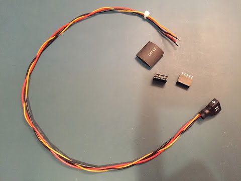
The power distribution board is connected to each of the backplanes/cards via a power cable which has the three wires (12V, Ground and Vd) braided together ending in two female 5 way connectors stuck together and heat shrinked which can then be plugged in to the right angled 10 way IDC connector of each backplane/card. Here is a picture of the Z power cable:
That’s it then, with the backplane and power distribution in place I can now demonstrate all of the parts of the computer constructed so far working together and that’ll be covered in my next post.