In a change from prior form I’m combining the construction and testing of the next card in to a single post this time. Partly because this card is a nice easy one but also because it’s the first card that I’ll be partially constructing to begin with and then I’ll return to it later to add further functionality.
The card in question is the decoder which will take the value on the instruction bus and use it to decide which instruction class it represents. This class will then be used by the upcoming control card along with the sequencer pulses to operate the various control lines of the computer in the appropriate order. To begin with the decoder will recognise MOV8, ALU and SETAB instruction classes but there’ll be more added later on.
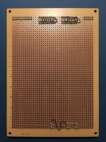
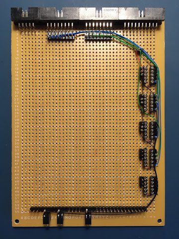
Diving straight in to the construction I start with soldering down the status LEDs:
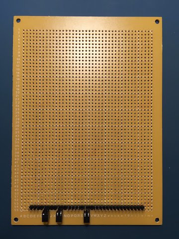
I’ve continued to use the same method of joining all the LED cathodes together with bits of trimmed off diode/LED legs as it takes the solder really well and is far less fiddly than any other method I’ve tried to date. One oddity on this card is the kynar wire link on the back of the card. This is a temporary ‘hack’ to bridge where a further LED will sit later on when more operation classes are added to this card.
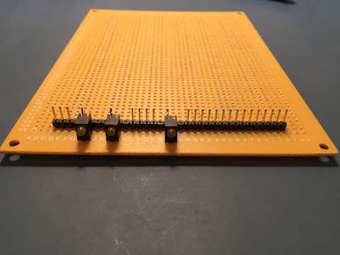
Next up are the card connectors:
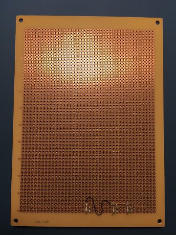
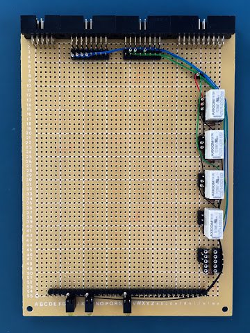
Then fast forwarding a bit I add the relay sockets, flyback diodes and power and ground lines:
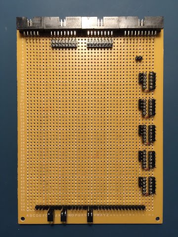
Again, there’s a temporary kynar wire linking the LED and relay grounds together … when further LEDs are added a more permanent connection will be soldered in.
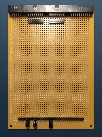
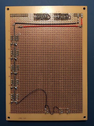
With the soldering done it’s on with the wire wrapping. There isn’t much to do on this card - just the LED links, ‘decision tree’ lines between the relays and then the inbound opcode bits and outbound instruction class lines:
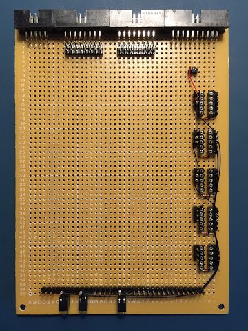
… and that’s pretty much it. With the relays popped in the card ends up looking like this:
As usual I’ve put a video together that demonstrates this card in operation. In this video I give a quick overview of the card and then demonstrate triggering the MOV8, ALU and SETAB decoded results.
That’s it for this card … at least for now. It has just enough functionality to enable the computer to perform copying values between registers, loading values from the opcode and performing ALU operations. Before any of that will be possible I’ll need to start constructing the sequencer … again though, just enough to operate these three 8-cycle instructions. The sequencer will also be a break from the relatively straightforward pair of cards constructed recently … so much so that the sequencer is spread over two cards as there’s a lot to fit in.