There’s been lots of theory going on in my recent posts but the time for design is over (for now) … it’s time to get constructing. The first card up in this batch is the instruction register and as it shares much of its design with the other register cards the construction is very similar.
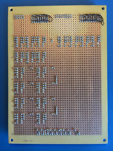
The first step is to solder down the LEDs. Here’s some pictures, front and back, of the card following this first round of soldering:
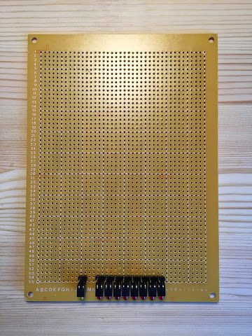
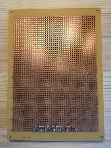
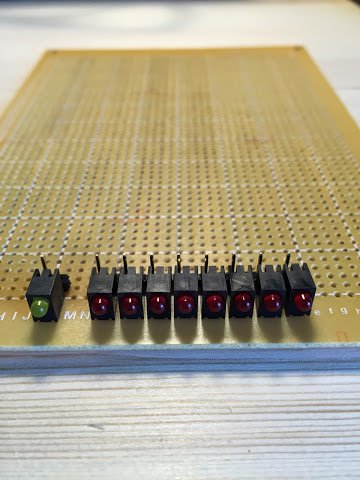
I’ve continued the trend of removing the negative wrapping post behind each LED again to make wiring up easier later on. I’ve also continued my ‘other trend’ of hunting for a good way of soldering up the cathodes on the LEDs … this time I’ve folded each cathode leg over a piece of trimmed off LED anode leg to create a bridge between several cathodes and then soldered everything down. This seems to be the best way so far and the solder takes to the LED leg better than the using a piece of wire to bridge the cathodes. Unless I come up with a better way of soldering these LEDs in I’ll stick to this method going forward.
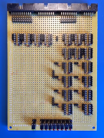
Following on from that the next job is to solder down the connectors, relay sockets and wire wrap posts. Front and back it looks like this:
… and then the ‘flyback’ and feedback protection diodes come in next …
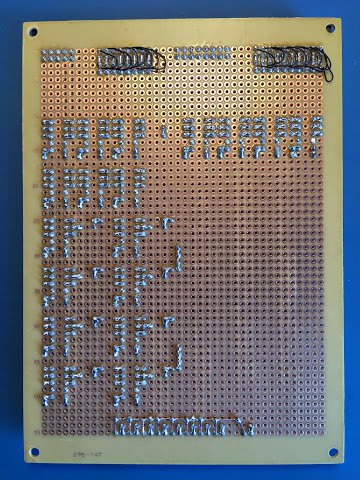
The final bit of soldering is to put down the power and ground lines on the solder side of the board:
I’ve still not got around to buying in some black wire for the negative lines so I’m still on the grey wire for now.
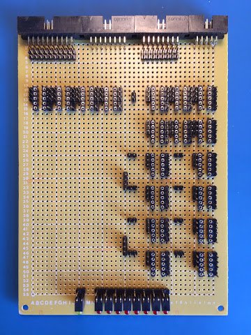
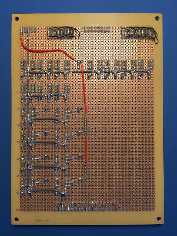
With all the soldering done the final steps are to lay down all the wire wraps. This is done in stages by laying down each family of related connections then laying the next family on top of that. Here’s four pictures of the wraps building up over time:
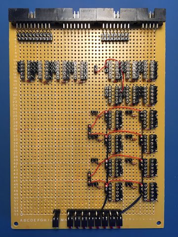
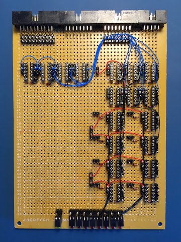
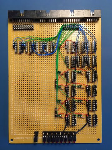
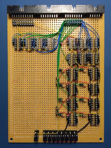
The top left picture shows the first three wraps: the black internal connections, black LED connections and the red power connections. The top right picture shows the next wrap: the blue data bus in/out connections. The bottom left picture shows the green result connections wrap added and the last wrap is shown in the bottom right picture which is the yellow control connections.
That’s it for the main construction of this card … all I need to do now is pop in the relays and then give it a try. I’ll cover testing the card in my next post and as usual I’ll put up a video showing the card working.