Now that the two display cards are complete enough to display and control the status of the ALU and four registers (A-D) it’s time to fit them to the upper enclosure. With that done the upper enclosure can then be connected to the lower enclosure and everything can be given a test together.
The upper enclosure is constructed very similarly to the lower enclosure … as before, out of aluminium profile. Here’s a Sketchup image of how the upper enclosure should look when sat on top of the lower enclosure:
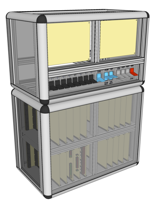
The two blank cards at the top of the upper enclosure are Display A and B (A on the left, B on the right) and as with the primary input switches below the display cards are attached to the enclosure by a frame of aluminium channel. Eventually I’ll be adding a connection board between the upper and lower enclosure so that the two can be split easily when the computer is moved around but for now everything is ‘hard wired’ together with ribbon cables.
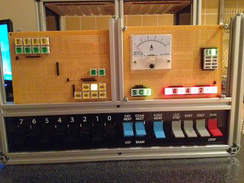
Here’s a picture of the upper enclosure powered up and working with the lower enclosure sat behind it:
As usual I’ve put together a video which shows everything built so far working together which includes a quick tour around the new upper enclosure so rather than me repeat all the detail here you can find the video below:
As mentioned at the end of the video I’m in the process of moving house now so construction on the computer is going to slow down for a bit but there’s plenty of design work to do in between decorating the new house. More generally I’m going to take a bit of a step change now and get the computer to a state where it can execute single operations automatically rather than by the operator setting the control signals for the ALU and registers by hand. This’ll take quite a bit of design and construction to do and will involve putting together initial/simplified versions of the clock, sequencer, decoder, controller and instruction register cards. Once these are done it’ll be possible to set an opcode on the instruction register and let the computer complete each instruction by itself. The next step from there will be to add a memory card, instruction pointer / program counter and associated handling to let the computer automatically execute a set of instructions stored in memory.