Now I’ve got a fully working ALU and four registers completed I want to take a short break from card building and turn my attention to making it easier to interact with the computer. Currently I’m controlling the computer via a set of DIP switches which is incredibly fiddly so it’s time to construct something ‘chunkier’.
The switches I’m going to concentrate on first are the primary data switches which permit values to be placed on the data bus. These switches won’t be directly connected to the data however because as a user you’d have to keep turning them all off so the computer can use the bus … instead I’ll build a gating circuit so the value on the switches can be placed on and off the bus as needed. Additionally the gating circuit will also allow the values on the switches to be gated over to the lower 8 bits of the 16 bit address bus. This will allow the quick setting of addresses once the computer gains its memory card and register. I was originally thinking of having a separate set of 16 switches for setting the address bus but decided in the end that I didn’t want to use the space up for something I didn’t think would get used that much. The upshot of this is that to set the upper 8 bits of the address bus requires gating the switches to the data bus and then loading the higher 8 bits on one of the 16 bit registers (like the upcoming M2, Y and J2 registers). That said, at the moment everything is manual until I build the data and address load circuitry so for now gating the switches on to the data bus would always be followed by a manual register load operation.
As for the style of switch I’m going to use … I’ve known exactly what I’m after ever since seeing the control panel of a PDP-11 … the biggest, chunkiest paddle switches. Although ‘other manufacturers are available’ I’ve settled on using switches from NKK in this computer and these in particular are from their ‘M’ series:
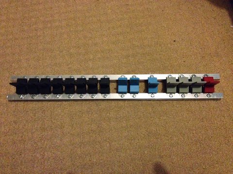
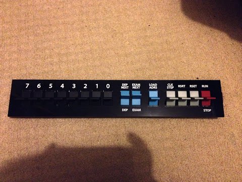
The data switches are on the left in the top picture … the set of eight black switches. I’ll leave the remaining switches for a later post but in summary these will control run/stop/reset/restart/clock-step and operate the load/deposit/examine functions. Each data switch is a SPDT and is stable in either the up or down position. I’ll be wiring these up so that when the paddle is down it represents a 0 and when up a 1 (which is fairly standard for ‘flicky-switchy’ computers).
I’ve mounted all the switches on two aluminium channels which are strong, lightweight and allegedly easy to machine/drill. On that point it took me several attempts and lots wasted channel and bleeding fingers before I attained knowledge of how to drill aluminium properly … which has also led to my favourite purchase of the year so far … (don’t laugh) … an automatic centre punch. Drilling is so much easier when the drill bit doesn’t go wandering around. Other than the essential centre punch I’d highly recommend lots of lubrication, a clamp/vice and not using a Dremel (it’s too fast even on the lowest setting) (in the end a cheap drill I got from Homebase for £15 has been perfect for the job). After several attempts I managed to drill some clean and precise holes so I could then install the switches:
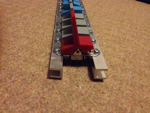
Each switch is held in place with an M3 screw and matching nut. I intentionally positioned the channel facing outwards so that it’s easier to hold the nut when doing up the screw. Additionally visible here are the two M4 holes which will connect this switch bar to an upright channel and then to the enclosure from there. With the switches in place I can now drop over the laser cut acrylic panel and surprisingly (see, no confidence in my machining skills) it fits nicely and doesn’t snag any of the switches:
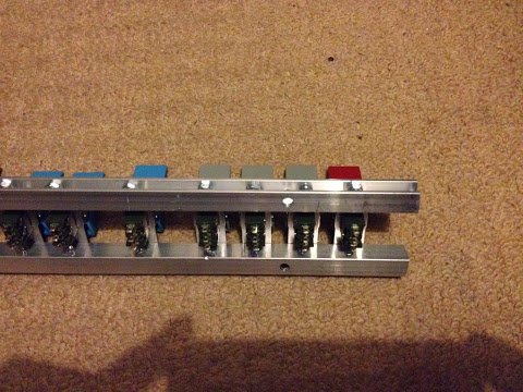
With the switches all securely fixed in place I then moved on to wiring them up. Embarrassingly (I’m too honest on here) I wired them upside down to begin with so on was off and off was on … my own fault for not testing how the switches work with the multimeter first. Rather than unpick the soldering I just turned the whole set of eight switches 180 degrees and refastened them to the aluminium channel. In the end it looks like this:
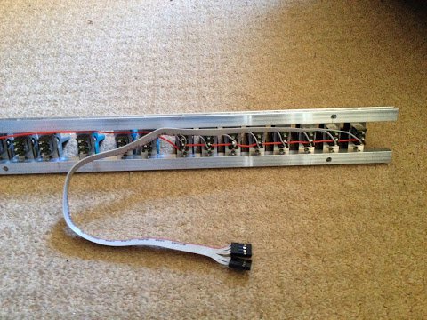
The switches have a common power supply and then each feeds back down the ribbon cable to the header pin socket at the end. These are crimp sockets and are another fiddly tedious job to endure.
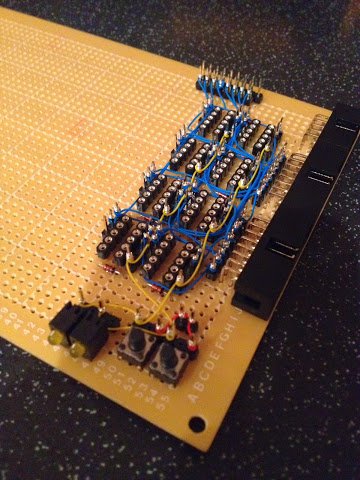
As mentioned at the top of this post I can’t just connect these switches directly to the data bus as it would block it from use by the computer itself so what is needed is some gating circuitry. This is relatively simple and very similar to the gating circuitry used elsewhere in the computer. Here’s the schematic for it:
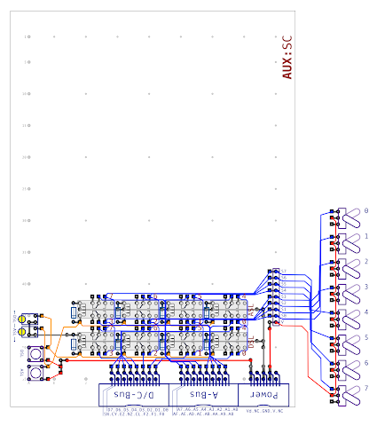
Most of this is hopefully self explanatory (if you’re accustomed to my schematic style) but effectively the switches are routed through two sets of relays. The top set gate on to the lower eight bits of the address bus and the lower set of relays gate on to the data bus. For testing purposes there’s two tactile switches to operate each set of relays. Something new is the Vd line on the power supply which only supplies power when the computer is in a ‘diagnostic’ mode. This mode enables functions that are only used for debugging and in this particular case the computer will eventually be able to gate these switches itself when it wants what’s on them but for now it’s all manual.
You might notice there’s an enticing amount of space left on the upper part of this card and of course there is something planned for this space but I’ll hold that back for a later post … needless to say this card will be full when it’s finally complete. As with previous schematics you can find a version here in PDF format should you want to take a very close up look at it.
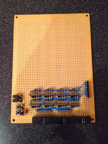
Construction of this circuit was fairly quick and done more or less in a single evening. There’s nothing special to mention here so I’ll move swiftly on to some pictures of it in it’s almost finished state (just needs the relays popping in):
I’ll give the control card and switches a whirl at some point over the weekend and then I’ll mount them in to the upper enclosure which I’m now ready to start building as I’ve received all the cut aluminium profile. Following that I want to take the first steps on constructing the two display boards which also sit in the upper enclosure. As always I’ll post progress on here in due course.