I haven’t posted in nearly a month but in between bouts of enjoying the rare British sunshine I’ve been plodding away at the A/D register card and it’s now finally ready for testing. The A/D register card is effectively a slightly simplified version of the previously covered B/C card and so a lot of the content in this post is going to be pretty similar. Despite this though I’ll go through all the steps taken to construct the A/D register card for the sake of completness … primarily in photos and then with extra text where anything odd or different came up compared with the B/C card.
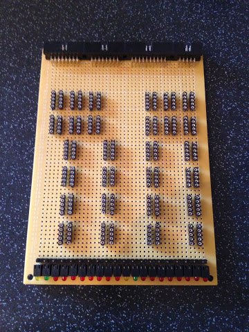
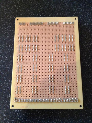
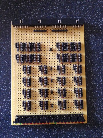
The first step was to solder down the LEDs and ribbon cable sockets. Here’s some pictures, front and back, of the card following this first round of soldering:
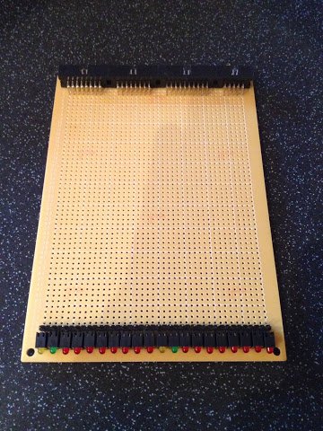
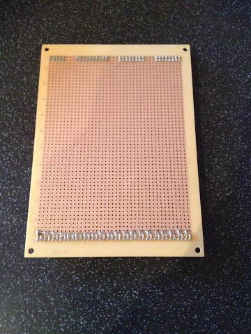
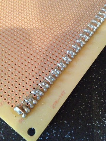
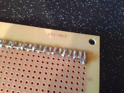
I’ve continued the trend of applying a line of super glue to the board when placing the LEDs (to stop them moving about while soldering) and I’ve also removed the negative wrapping post behind each LED again to make wiring up easier later on. Continuing the usual theme of mishaps in this area I’ve had yet another go at trying to find a nice neat way of soldering up the cathodes on the LEDs … this time I’ve folded the cathode leg over a piece of wire and then soldered it down. This seems a bit better but the solder doesn’t always take that well to the wire so I’ve had to resolder a couple of the joints a few times. Close up it looks like this:
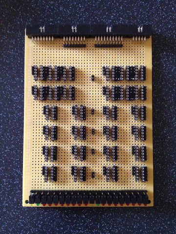
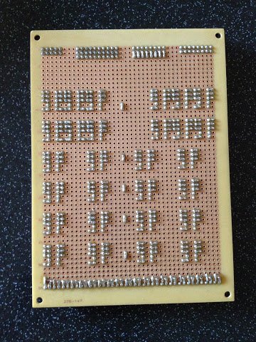
Following on from that the next job was to solder down the relay sockets and again I’ve used the two rows of 5 pin sockets which proved successful on the B/C card. Front and back it looks like this:
Next up is the wiring wrapping header pins …
… and then the ‘flyback’ protection diodes come in next …
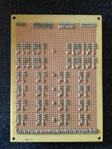
This final bit of soldering was to put down the power and ground lines on the solder side of the board:
This stage was pretty much consistent with previous cards so nothing new to mention here other than I’d run out of black wire for the negative lines so I’ve moved on to my stash of grey wire (it’s a kind of black after all).
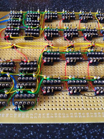
With all the soldering done the final steps are to lay down all the wire wraps. This is done in stages by laying down each family of related connections then laying the next family on top of that. Here’s four pictures of the wraps building up over time:
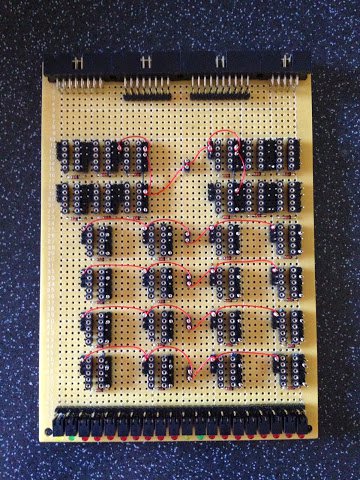
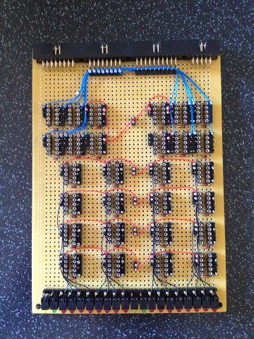
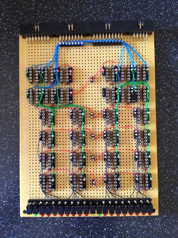
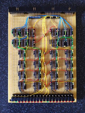
The top left picture shows the first two wraps: the black internal connections and the red power connections. The top right picture shows the next two wraps: the blue data bus in/out connections and the black LED connections. The bottom left picture shows the green internal result connections wrap added and the last wrap is shown in the bottom right picture which is the yellow control connections.
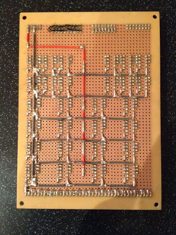
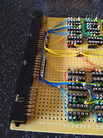
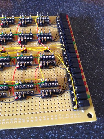
Finally here is three close up pictures of the final wire wraps:
That’s it for the main construction of this card … all I need to do now is pop in the relays and then give it a try. I’ll cover testing the card in my next post and as usual I’ll put up a video showing the card working although this time I’ll probably just skip (in the video) to testing in the enclosure alongside the other cards being as the A/D register is so similar to the B/C register.