As mentioned in my last post I decided this time around not to post after each stage of card construction (being as the construction steps are now pretty similar to those for previous cards). In line with that decision this post covers all the steps taken to construct the B/C register card … primarily in photos and then with extra text where anything odd or different came up compared with the other cards completed so far.
The first step was to solder down the LEDs, ribbon cable sockets, relay sockets and finally the wire wrapping posts. Here’s some pictures, front and back, of the card following this round of soldering:
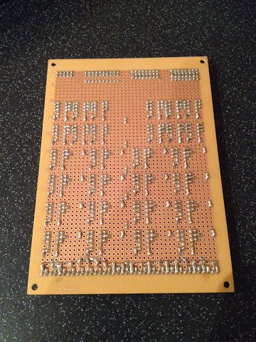
I made a few tweaks to the construction method on this card. Firstly I applied a line of super glue to the board when placing the LEDs to stop them moving about while soldering and this has kept them more or less pointing forward. Also with the LEDs I’ve removed the negative wrapping post behind each LED to make wiring up easier later on (and to avoid shorts when testing around the LEDs). As usual I’ve still not found a nice neat way of soldering up the cathodes on the LEDs so this card looks a bit of a pig’s ear as always.
This time I’ve also made a small change to the layout of the relay sockets. On previous cards I’ve used three sets of triple pin sockets laid out in a ‘U’ shape. This has always been a bit fiddly and time consuming so I’ve simplified things this time by just having two rows of five pin sockets. The same relays will still be used but whereas before the bottom middle socket position was unused/unconnected now the two positions one up from the bottom on the left and right are unused. This means wasting one extra socket per relay from the strip of 32 (and those turned pin sockets aren’t cheap) but it saves loads of time and frustration when soldering the sockets down.
This card also has extra diodes (in addition to the usual ‘flyback’ diodes over the relay coil) to stop back feed on the B and C bus lines. At the end of each of these back feed diodes is a single wire wrap post. These were particularly tricky to solder down and so some of these are a bit wonky … the posts tended to get wonkier as my finger got progressively more burnt. I think in future I’ll try and ensure I always solder these posts down in pairs (like the ones up the middle of the card) so I can hold the part in place from one side whilst solder tacking the other side down.
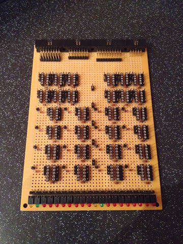
Here’s a picture of the LEDs viewed from the front:
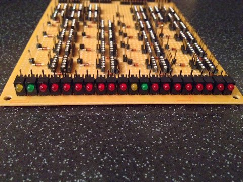
The left ten LEDs are for register B and the right ten for register C. Each have the same read-out with the left most LED showing when the register is being loaded (yellow) and then the next showing when the register is being selected (green) and then the following eight LEDs show bits 7 down to 0 (in that order).
The next stage of construction was soldering down the power and ground lines on the solder side of the board:
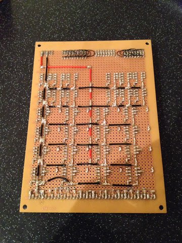
This stage was pretty much consistent with previous cards so nothing new to mention here other than I had to skirt around the messy soldering on the LED cathodes to avoid any shorts (this is particularly evident on the photo above at the bottom left where the black wire curves upwards).
With all the soldering done the final steps are to lay down all the wire wraps. This is done in stages by laying down each family of related connections then laying the next family on top of that. Here’s four pictures of the wraps building up over time:
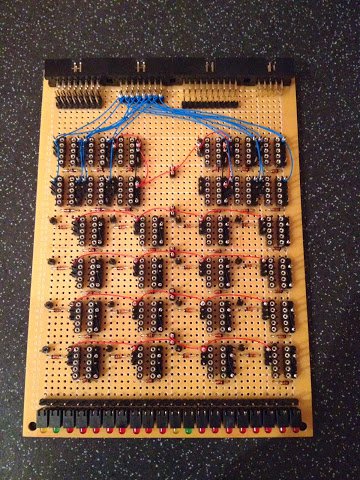
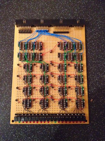
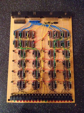
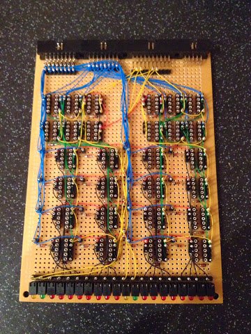
The top left picture shows the first three wraps: the black internal connections, the red power connections and blue data bus in/out connections. The top right picture shows the next two wraps: the black LED connections and green internal result connections. The bottom left picture shows the next wrap which is the yellow control connections and finally the bottom right picture shows the final wrap which is the blue B and C data connections.
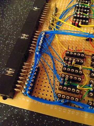
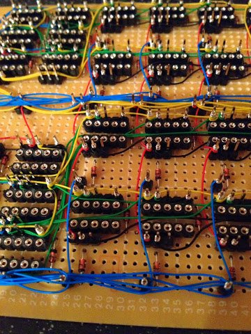
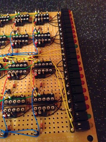
Finally here is three close up pictures of the final wire wraps:
That’s it for the main construction of this card … all I need to do now is pop in the relays and then give it a try. I’ll cover testing the card in my next post and as usual I’ll put up a video showing the card working but also I’ll show the card placed in the enclosure and connected to all the cards constructed so far.