I’ve been promising this post for quite a while now … an update on how the enclosure construction is going. Well, it’s very good thanks :)
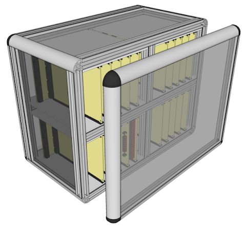
Firstly, here’s a quick reminder of the SketchUp design showing how the enclosure should look:
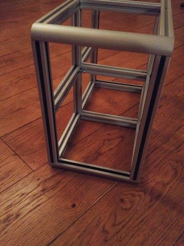
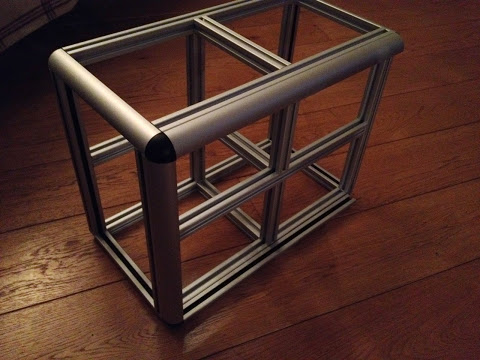
… and here’s how it looks, so far, in reality …
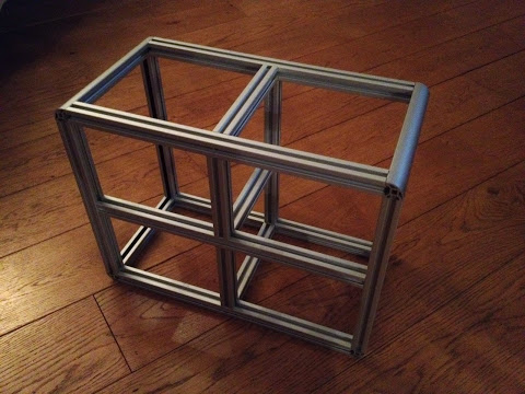
This is the main frame of the card enclosure and you can see it forms four compartments that will hold five cards each plus backplanes. At the moment the front and back doors are incomplete as they’re waiting for the perspex/acrylic sheet (3mm smoked transparent) to be cut. Likewise the perspex that fits in the sides of the main frame are also pending. Because of this the frame as it appears above isn’t fully screwed together yet … the back bars (which kind of form a shape like two ‘E’s back to back) are just held in by friction on the corners. Once the side perspex panels are in then everything can be screwed together and a very rigid strong frame results. All the joints are held together with self tapping torx screws which are driven into the end of a piece of profile and then the screw head rests in the slot of a second piece of profile and is tightened with a screw driver via a drilled access hole.
I’m particularly pleased with the finish of the aluminium profile I’ve used for the enclosure — it’s really high quality and strong yet relatively easy to machine and work with. In putting this together I’ve had to learn some metal working skills … like how to drill metal without breaking the drill (or my hands) … but effectively it’s all relatively straightforward stuff. One thing I’ve definitely learnt is to use WD40 for everything, especially when driving the self tapping screws in … it took a couple of days for my hands to stop throbbing after trying to drive the screws in without lubrication.
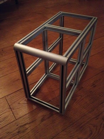
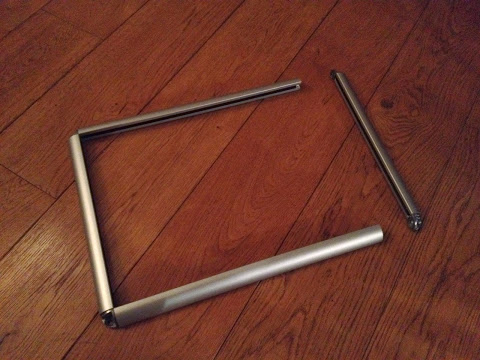
Here’s some more pictures of the frame:
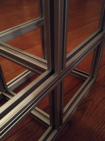
One thing you might be able to see on the pictures above is the black insert that runs inside the left and right side edges. This is a snap-in plastic mounting rim which will hold the perspex panel in place. A nice feature of this plastic rim is it’s reversible so you can rotate it 180 degrees and use it as a blanking strip. This keeps dust and muck out of the exposed profile slot and also hides the access holes drilled to tighten the connecting screws. You can see the strip used in this way in the pictures above running vertically on the corner profiles.
For the enclosure doors four pieces of rounded profile are joined together using corner brackets which looks like this:
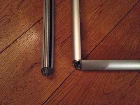
The door hasn’t been fully screwed together yet as it’s also waiting for the perspex sheet which will sit inside this frame and as with the main enclosure frame the plastic mounting rims are installed in the profiles for carrying the perspex sheet when installed. One thing I will say about these doors is that they represent the most expensive part of the enclosure and it’s mainly down to those corner brackets … they come in at around £3.75 each which is fine until you realise you need eight of them (four per door) and then the caps which cover the brackets come in around £1.30 a corner. In hindsight I could have gone with a non-rounded door as a cheaper option but the choice I’ve ended up going for does look much nicer and I guess you have to pay for that ;) Incidentally, metal profile in general isn’t a particularly cheap method of construction … the enclosure as you see above has come to around £145 (although 20% of that goes to the government of course in VAT). Oh, and actually £24 of that is on 70 T4 nuts which sit in the profile slots so I can attach the various card supports and so on.
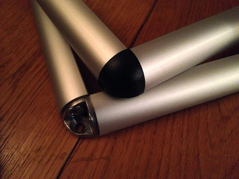
So yea, quite a lot of money to spend on an enclosure but even though it’s not quite finished yet I personally think it looks really good. Here’s some more pictures to hopefully get across its good looks (this time with a corner cap installed on the door brackets):
I keep mentioning the perspex that I’ll need to complete the enclosure … this might take a little bit of time to arrive … mainly because I’ve not ordered it yet … I’m waiting for a free delivery offer from the laser cut company (which they do from time to time) as otherwise it’s a fairly hefty charge. It might seem odd using laser cut for what should effectively be a rectangular piece of perspex, and it’s true just buying straight cut perspex sheet is definitely cheaper, but the doors require a bit of an odd cut due to the corner brackets blocking out the corners. As such I actually need a perspex sheet that has corners cut like this:

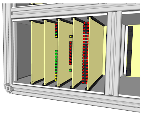
This forms the ’tabs’ that will sit in the plastic mounting rim but allows for the corner bracket which takes an additional 3mm up due to some locating lugs which help keep the bracket positively lined up with the profile edge. The easiest and cleanest way to achieve the shape above is with laser cut - I simply upload a file detailing the shape to cut and several days later the cut perspex arrives in the post. There’s also another reason for getting the perspex via the laser cut route … I have something else I want cutting too … each of the four card bays in the enclosure needs a floor and ceiling that will carry the card guides. Here’s a SketchUp drawing showing the floor and ceiling in place:
Although the floor/ceilings are pictured here as a simple board the real thing will need to be cut around the aluminium profile, have holes drilled for fixing to the profile and to fit the card guides, have slots to feed ribbon cable though and finally have ventilation slots. These floor/ceiling boards will be made from 3mm thick plywood and these are definitely easier to get laser cut given what a pain it’d be to hand cut eight of these. Here is the laser cut lines:
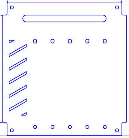
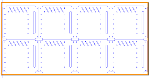
The four holes in the corners are for bolting the board to the aluminium profile with the remaining holes taking the card guides. At the top is a slot for passing ribbon cables though and the diagonal slots are for ventilation. As mentioned there are eight of these boards in total, all identical, and so the full cut file is as follows:
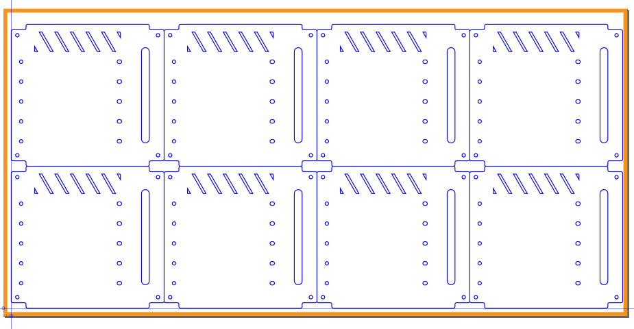
The orange outline here defines the cuttable area from the preset sheet size. One thing worth noting on the cut images above is that I’ve thickened the lines up so they’re easier to see here — for cutting the lines need to be set at 0.01mm (plenty thick enough for a laser beam).
Right, that’s enough for this post (I’ve gone on far too long). I’ll post on the enclosure again when the perspex and floor/ceiling boards are in. For now I’m back working on the backplane for the ALU cards and I’ve suffered a bit of a set back due to some poor design decisions that’s meant I’ve had to throw the whole backplane card away and start on a new one with a different design. Needless to say I’ll reveal the whole sorry tale in an upcoming post.