Following on from the first two successfully completed ALU cards, for logic and arithmetic, it’s time to make a start on the control card (well, actually, the LEDs and connectors are already done from earlier but you get the gist). The control card performs three functions: control registers, function decoding and zero detection … and thankfully this card is much simpler than the previous two in terms of relay count and sheer amount of soldering so should come together relatively quickly.
So, I’ll start with some pictures of progress so far:
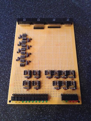
Looking at the first picture the sockets for the zero detect relays are down the left hand side of the card, for the function decoder bottom left and condition registers down the bottom right.
Unfortunately I’ve made a right royal balls up with the zero detect relay sockets … apparently unable to read my own diagrams I’ve mis-aligned the sockets. Each socket should be positioned so that one of the normally-closed switches of one relay flow in to those of the next relay and so on. This then creates a chain of closed switches which is broken if any one relay is turned on thereby making the zero detect circuit. Fortunately I can solve this by soldering down some wire links (which is much easier than desoldering multi-leg/pinned components).
Next up for this card, after the remedial links described above, will be the power rails and then it’s straight on to wire wrapping.
Oh … I couldn’t resist buying the aluminium profile for the case so expect a post in the not too distant future showing the first part of the case in real life.
Oh … and whilst I wasn’t resisting buying profile I also decided to not resist buying some nice chunky toggle switches (plus LEDs and other bits and bobs for some of the upcoming cards) … needless to say I’ll probably be eating soup for the rest of the month.