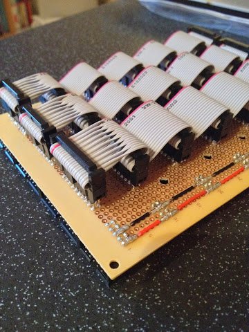
In my last post I mentioned I’d suffered a bit of a set back with the construction of the ALU backplane. Well, the short version of things is that I’ve admitted defeat and constructed a new backplane using a different design … it looks like this:
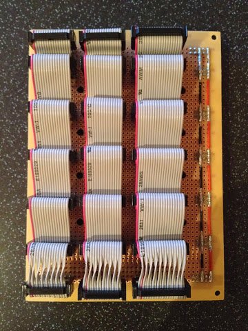
This design uses stackable headers instead of regular sockets so that the pins extend out of the back of the card far enough to attach an IDC connector. Each of these connectors can then be ‘daisy chained’ together with ribbon cable making construction relatively quick and easy to do.
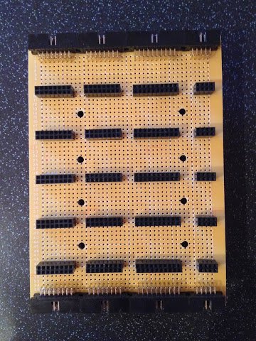
So, what went wrong with the original backplane? Well, it was one of those cases where it worked fine on paper and in my head but not quite so in reality. This is where the original card ended up:
In this design the regular sockets have header pins soldered alongside on the back of the card. The idea was that I could then take a length of wire and wrap it around each post soldering as I go. It dawned on me, as I made a start on the wiring, that this was going to be an incredibly fiddly job (mainly down to faffing around with the wire insulation to keep the nearby bare wires from shorting) but I carried on undeterred. It was after soldering a couple more connections when physics took over and reminded me who’s the boss … the problem being is that the more connections are soldered to the wire the more metal there is to wick away the heat of the soldering iron. Eventually there’s so much metal to heat that the soldering iron gives up trying and it’s no longer possible to melt the solder.
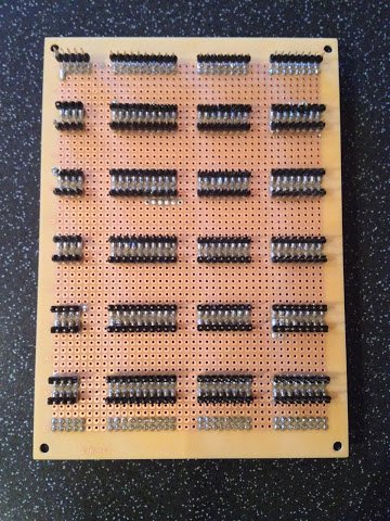
I considered some ways of salvaging the backplane but in the end decided the quickest and easiest route was to start a new backplane with a new design that circumvented all that soldering. Here’s a close up picture of the new backplane:
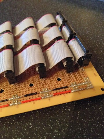
The power connectors are simply connected with soldered wire links but everything else is connected with ribbon cable. These were reasonably simple to construct … the main thing to watch out for was getting the spacing between the connectors right. Here’s another close up from the other end of the card.
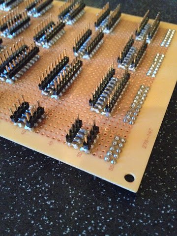
There’s a slight oddity down this end which is due to another design anomaly. The backplane is designed to take a set of bus lines in at the bottom of the card and send the same bus lines out at the top. For regular straight boxed headers this isn’t a problem — if pin 1 is on the bottom left at the bottom of the card then it’ll be on the bottom left at the top of the card. However, this card uses right angled boxed headers to cram more in on the card but this has the effect of flipping the lines vertically so whereas pin 1 is on the bottom left at the bottom of the card it’ll come out on the top left at the top of the card. The fix for this is to twist each pair of wires on the ribbon cable to counter this effect and that’s what can be seen in the photo above.
I may still try and find a way of finishing the old backplane rather than throw it away but I’ll leave that for another day. In the meanwhile though I’ve ended up with a working backplane which means I’m now finally in a position to connect all three ALU cards together and test everything working together.