I’ve just realised that as I’ve been constructing the first ALU card I’ve not given much thought to how I’ll actually test the card (or other cards for that matter) when complete … this post therefore represents a quick aside to tackle testing.
What I’m looking for is a small board with enough switches on it to drive the various inputs of each card … ideally it’ll be reusable between cards and easy to use. I did originally think of using DIP switches but they’re a bit on the fiddly side so I’ve gone for tactile switches instead — the main problem with these is that they’re non latching but I figure that I won’t need to push more than 10 buttons at a time hopefully.
There’s not a lot of planning gone in to this one … I just grabbed the bits from my parts box and set off soldering (sometimes it’s nice just to get stuck in rather than planning everything ;) The result looks like this:
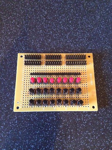
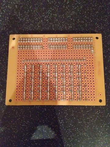
The three rows of buttons have no fixed purpose and a wire link is used to configure/connect the buttons against the header pins at the back. For the ALU cards the button rows, from front to back, will be configured as Input B, Input C and Control. You might notice that this picture is a bit brighter than my usual ones as it’s taken in the daytime for a change … quite a rate thing being as this hobby tends to be a weekday evening thing. The solder side looks like this:
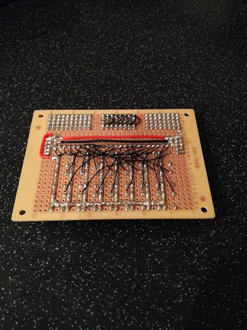
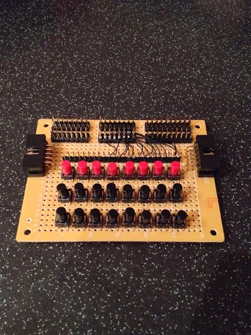
Following this I later added two extra boxed headers to run the power and ground through the board from the power supply and on to the card under test. I also added some initial wire links between the buttons and the header pins. Front and back end up like this:
Next post I’ll get back to finishing the soldering on the logic card so I’ll actually have something to test.