Originally when I was thinking about how I’d
connect up the various cards of this computer I had ribbon cables in mind.
Ribbon cables are straightforward to use and physically flexible which would
allow me to work out how I’d physically arrange the cards later on. However,
the more I thought about it the more I liked the idea of using a backplane
that the cards would slot in to — a bit like those 19 inch server racks that
take CPU cards. This would also give the cards some physical support so I
could test several cards together with the whole thing freestanding.
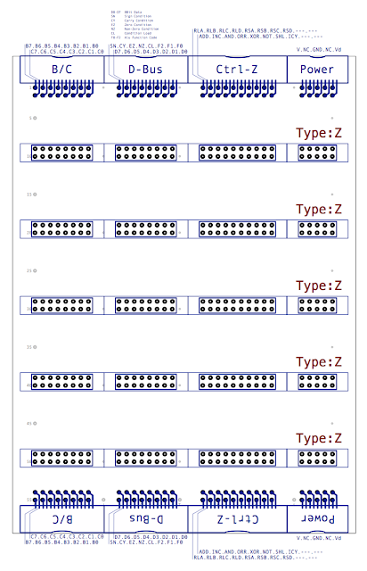
Design-wise there’s not much to it (also available here in PDF format):
The connectors at the top and bottom of the card are right-angled boxed headers and are the same as used on the three ALU cards (Logic, Arithmetic and Control). The connectors running up the middle of the board are header pin sockets that match the size and position of the boxes headers on each of the cards. These carry the same signals through the board as a bus so that any card plugged in to the backplane receives the expected signals. The idea is then that multiple backplanes can be connected together by ribbon cables using the boxed headers. This then means that when I finally put everything together in a case I can either have two backplanes side by side or stack them vertically.
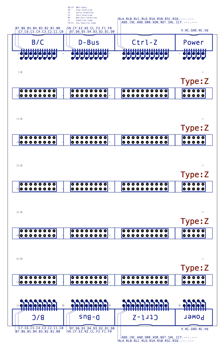
Something you might have noticed on this diagram and on other cards is the label ‘Type:Z’. This refers to the type of Control bus (which is the third connector from the left) which is the 20 pin connector that carries the various control signals that pass between the cards. So far all the control signals required by the ALU cards fit within the 20 pin connector. What hasn’t been covered in this blog yet are the general purpose registers A, B, C and D which use most of the remaining pins on this connector. The other cards that make up the computer will need other control signals but won’t necessarily need to talk directly to the ‘Type:Z’ cards and so will have their own ‘Type:Y’ or ‘Type:X’ connectors. The new control lines, additional to the ones already introduced on the ALU cards, are:
- RLA … Register Load A
- RLB … Register Load B
- RLC … Register Load C
- RLD … Register Load D
- RSA … Register Select A
- RSB … Register Select B
- RSC … Register Select C
- RSD … Register Select D
It turns out that that everything therefore works out quite nicely as the five cards (ALU Logic, ALU Arithmetic, ALU Control, Register AD, Register BC) all use the same connectors but also fit nicely if slotted into the backplane side by side with plenty of head room on each card for the relays. This seems to be yet another one of those happy coincidences that I keep coming across with these pad board cards where everything comes together and just fits.
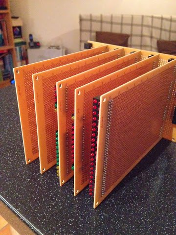
The initial construction of the backplane is fairly trivial … just a case of soldering down all the connectors … and it looks like this:
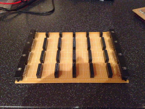
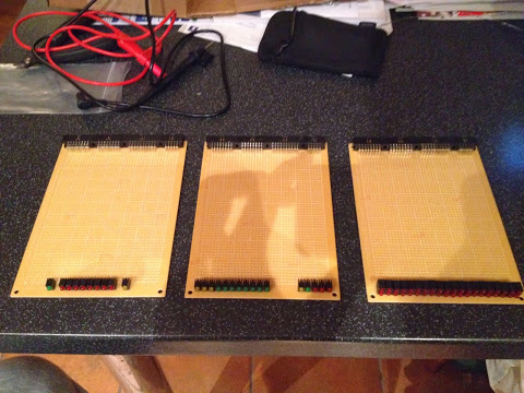
The wiring between the connectors will be done on the solder side of the board to keep this side free of anything that could obstruct the other cards. I’ll add the wiring later … probably after constructing the three ALU cards when I need to test them all working together. Just for a quick reminder, the three ALU cards in their current state of construction look like this:
So, when plugging the ALU Cards into the backplane (along with the two register cards which currently only have the right-angled boxed headers on them for now) this is the result:
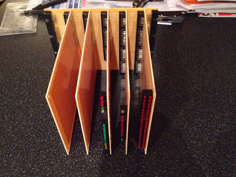
Note that because the connectors are identical all the way up the backplane the cards can go in any order desired. I think it’s fair to say that whoever came up with the boxed header connectors probably didn’t envisage them getting used in quite this way but it does the job and it’s certainly a ‘positive connection’ … in fact it’s such a positive connection that once the cards are in they take a fair amount of force to remove again. The key thing when removing the cards is to apply even pressure to avoid breaking the card or connectors (or both). I’m thinking that when I eventually put all this in a case I could put some plastic tabs at the two front corners of the card that can be lifted and levered against the case to pull the card out steadily and straight. In the meanwhile … I’ll try to organise my construction so that I’ll only plug them in to the backplane when each card is complete.
Right, with that small diversion out of the way I can get back to constructing the ALU cards.