Finally, with all the soldering now done, it’s time to set about wire wrapping the ALU logic card. First up is the internal connections within each logic bit:
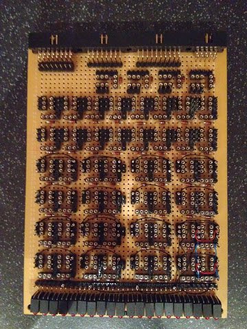
After wire wrapping a new set of wires I always run the multimeter over the board to double check everything is connected as intended. Again though, if there are any mis-wirings it’s trivial to correct — just unwrap the wire and wrap in a new one. There is a bit of skill required to get a ‘perfect’ wrap (where a bit of the insulation is taken around the post followed by nice tight coils above that) and mine are certainly not all perfect but bad ones can always be re-done.
Next is the internal power links in each logic bit and the links taking the results from each bit down to the LEDs:
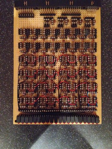

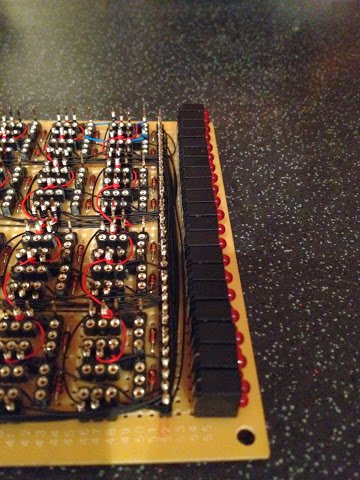
It just so happens that when using my multimeter in the diode test mode it passes enough current to dimly light the 12V LEDs which makes checking the display link wiring just that bit easier (and without the annoying bleep which it makes when there’s no resistance on the link being tested).
Next post will be more of the same … adding input and result links.