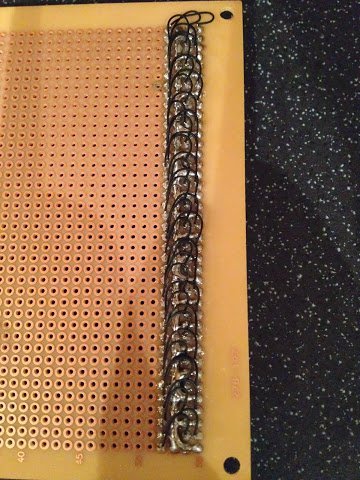
Before I can test all of the LEDs laid down so far (to make sure they survived the heat of the soldering iron) I need to add some wire links on the logic card between the LED anodes and the header pins. This isn’t needed on the arithmetic and control cards as they only have a single row of LEDs and so are soldered directly to the header pins but on the logic card, which has two rows of LEDs, the ’negative rail’ sits between the LED anodes and header pins.
To make the wire links I’m using the same 30AWG Kynar wire I’ll be using later for wire wrapping. This is a bit fiddly due to the size of the wire but not bad once you get the hang of it. With the links in place the logic card now looks like this:
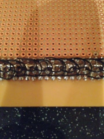
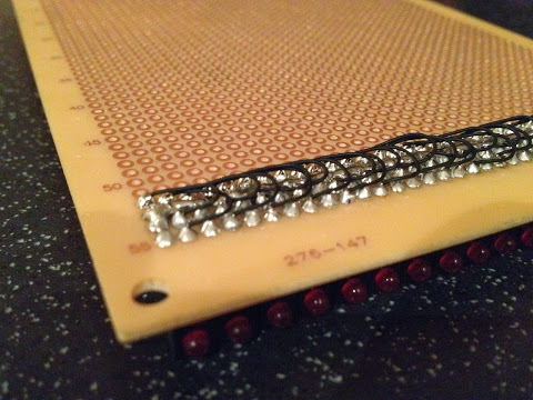
I’ve also tidied up some of the uglier solder joints whilst the ‘iron was hot’ (although the results still won’t win any beauty contests).
I should now be able to test the LEDs (fingers crossed) … I’ll take some videos of the results and post them up next.