The construction of the ALU logic card is coming along nicely but there’s still a lot of soldering ahead to get all the relay sockets down … and this part is the fiddliest bit yet.
The biggest issue I’ve found getting the sockets in place is that unlike the header pins, which tend to stay in place on the board whilst you solder them, the sockets will keep falling out. Usually if I’m soldering components down I’ll work in order of height from shortest to tallest so that when the board is turned over the components have nowhere to go … unfortunately because I started with the LEDs first there’s nothing to hold the sockets in place when soldering. To get around this I’ve had to develop a new skill where I hold the socket in with a finger on one hand and then pick and place a blob of solder with the other hand (remembering which pin I’ve got my finger on to avoid a nasty burn). Needless to say I’ll try and make sure I do things in the ‘right’ order on the other cards ;)
Anyho, after lots more soldering (and the occasional burnt finger) the logic card now looks like this:
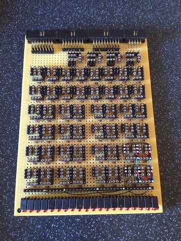
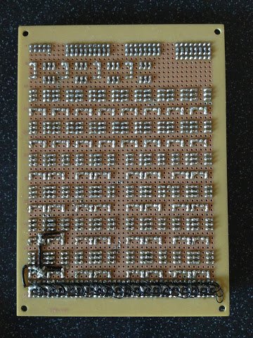
Oh yea, I’ve added the diodes (at each relay for protection) whilst I was at it too. Nearly there soldering wise now … just the power and ground links to put in and then it’s on to the wire wrapping. The underside of the board is looking quite attractive now IMHO (or at least it has a certain something about it).