It seems that every time I move on to the next stage of construction on the ALU logic card it’s fiddlier than the stage before it … this stage is no exception. This time I’m adding the power and ground rails that run around the solder side of the board. I’ll start with a picture of how it looks:
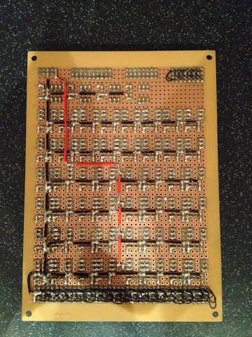
The really, really, fiddly bit this time is cutting all those lengths of (solid single core) wire to the required length and then stripping the insulator, bending the ends and soldering down — nothing complex … just fiddly. As part of adding these rails I’ve laid down some additional header pins up the middle of the board to get power to the relay gates as needed. Following usual convention the 12V power rails are in red and the ground rails are in black.
That pretty much wraps it up for the soldering work on this board. I’ve given the board a quick initial clean with some PCB cleaner to remove all the rosin residue (embarrassingly enough I’m not sure if the solder I’m using is no-clean or not so I’m cleaning it just in case — I will ask my supplier BitsBox at some point to find out for sure). It’s now time to make a start on the wire wrapping so my next post will be about that.