So far, in the construction of the three ALU cards (Logic, Arithmetic and Control) I’ve soldered down the connectors and LEDs. It’s now time to solder in some header pins and join them to the existing connectors and LEDs ready for wire-wrapping later.
You can get proper wire-wrap posts but they’re really expensive for what they are (mainly, I guess, because it’s quite an old-fashioned construction method). I’ve found, though, that header pins do the job just as well but being as they’re not as tall you can only get a maximum of two wraps on each pin. Incidentally, I’ve chosen wire-wrap for most of the cards inner connections as it allows easy and quick modifications and correction of errors (something that can be quite difficult with soldered connections or pretty impossible with etched PCBs). Additionally, I quite like the finished look you get with wire-wrap.
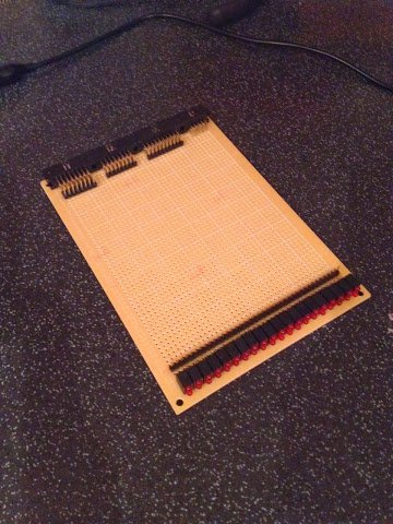
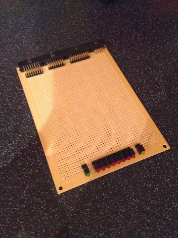
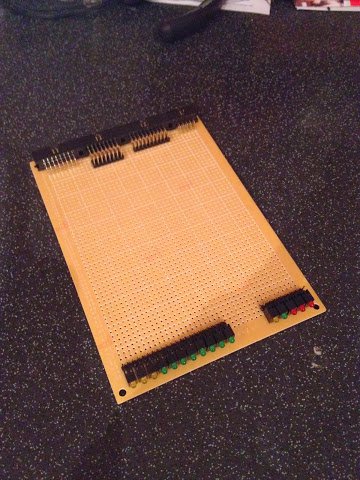
With the header pins added the three ALU cards look like this:
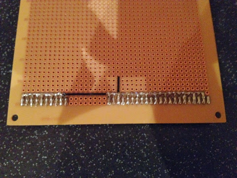
Soldering the header pins themselves is fairly straightforward but to link them to the connectors and LEDs I make solder bridges between the two pads as needed. This is all fine until you want to link a line of pads together (like when joining the cathodes of the LEDs together forming a ’negative power rail’) … as more pads are joined together the heat from the soldering iron gets wicked away so it gets harder and harder to keep the solder melted and moving (even with my relatively powerful soldering iron). Again, this is mostly down to me doing things unconventionally so I can’t moan too much. This is the underside of the logic card:
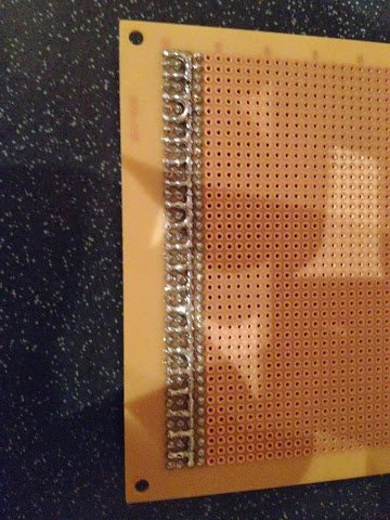
The cathodes of each pair of LEDs are joined together and then there is a line of joined up pads on the third row (viewed from the front of the card). As you can see, it’s not the tidiest soldering in the World but, again, it does the job. For the arithmetic card I tried placing a piece of wire down across the pads first to see if that made it any easier to solder in the negative rail but it actually just wicked away the soldering iron heat all the more. Here’s the result:
For the larger leaps on the negative rail I’ve placed insulated single core wire which gives a neater result but the rest of it’s pretty messy. I’ll no doubt do a bit of clean up on the solder joints later but I’m a little cautious not to kill the LEDs by overheating them.
As the logic card currently stands I can’t quite test the LEDs yet as I’ll need to put down some wire links between the header pins and LED anodes - I’ll move on to that next.