As promised in my last post it’s finally time to get the soldering iron out and make a start on constructing the three cards that make up the ALU. I’m going start by laying down the connectors and LEDs on each card to make sure I’m happy with the look and feel of things and then I can move on to everything else needed later.
As mentioned in earlier posts I’m basing my construction around 55 x 40 hole pad boards which fit my designs quite nicely at the right sort of size I’m looking to construct at. The connectors are right angled box headers and are simply soldered down to the back of the boards whilst the LEDs run along the front. The LEDs themselves are 3mm 12V types so that an additional resistor is not required (which would make the ‘crammed in’ Logic unit design even more tricky) and to make construction a bit more manageable each LED sits in a right angled holder.
Speaking of the LED holders, I was hoping to get hold of the ones that can be joined together to keep everything nicely lined up but was finding these tricky to get a supplier for so plumbed for the regular ‘free-standing’ ones in the end. I found, after much head scratching, that the easiest way to get everything to line up was to place each holder with LEDs fitted on to the board and then place packing between and behind each (braced against a strip of non-soldered header pins) and then solder the whole lot in one go.
I had a go at the simpler Arithmetic Card LEDs first and here’s the result (with design diagram for reference):
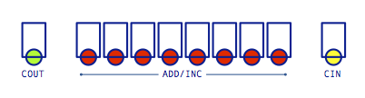

As you can see it’s not looking too bad and the LEDs are pretty well aligned. I’ve also soldered down the connectors but they’re fairly straightforward to do so there not much to say there. Moving on to the Control Card:
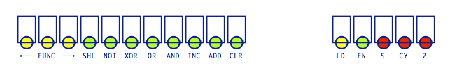
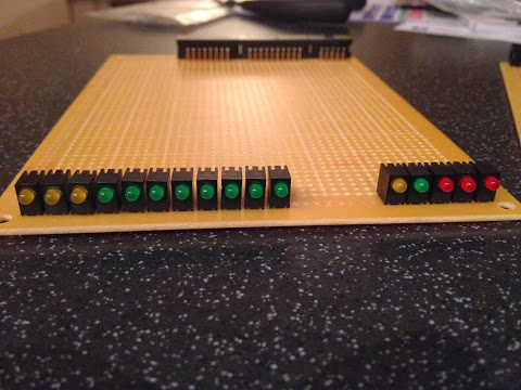
I wasn’t quite as successful with these ones and you can see that post-soldering some of the LEDs have taken on a bit of a slant to the left. It’s not quite as noticeable when you’re not close up to them though so I’m not too worried about trying to correct them. Finally then, and after ‘practicing’ on the other cards it’s time to attempt the LED fest of the Logic card. This time the holders are bi-level so are a little more stable to work with but needs twice the amount of soldering:
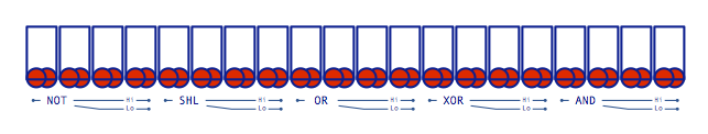
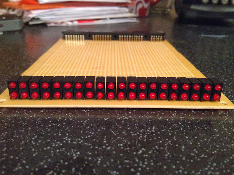
Again, not perfect but good enough … it’s a shame I couldn’t get hold of the ’linkable’ holders as it would have produced a really nice tidy result. One thing I have noticed about the Logic card LEDs is that it’s not easy to visually separate the five sets of 8-bit results. I could do with adding a piece of differently coloured plastic or something similar after every fourth LED to separate them a bit - I’ll add something later.
So, after all that soldering how many LEDs survived? Well, all of them as luck would have it … appears my soldering skills aren’t as dodgy as I thought (or LEDs have become tougher with advances in technology) … believe as you will ;) I’ve taken a video of the LEDs on the Logic card being tested … you’ll just have to trust me that the others work as it’s not all that quick to take videos, run them through iMovie and then upload them to YouTube:
That’s enough for this post … it always surprises me how much solder I get though and this has been no exception so far and there’s much, much more soldering to go. Before I do add more to the ALU cards though I’m going to take a small break and put a bit of thought in to how I’m going to connect the cards together.