This post covers the design of a 3-to-8 Function Decoder which along with the Zero Detect circuit and Condition Registers will all go in to the ALU Control Card. The Decoder takes a 3-bit ALU Function code as its input and activates 1 of 8 control lines accordingly. The function codes are as follows:
| Code | Operation | Description |
|---|---|---|
| 000 | CLR | Clear/No Operation |
| 001 | ADD | B + C |
| 010 | INC | Increment B |
| 011 | AND | B AND C |
| 100 | OR | B OR C |
| 101 | XOR | B XOR C |
| 110 | NOT | NOT C |
| 111 | SHL | Shift Left B |
The control lines which are fed to the Arithmetic and Logic Units via the Ctrl-Z bus are:
| Operation | Description |
|---|---|
| ADD | ALU Add Output Enable |
| INC | ALU Increment Output Enable |
| AND | ALU AND Output Enable |
| ORR | ALU OR Output Enable |
| XOR | ALU XOR Output Enable |
| NOT | ALU NOT Output Enable |
| SHL | ALU Shift Left Output Enable |
Note that there’s only 7 lines here as the control line for CLR produced by the 3-to-8 decoder is left unconnected — this is because if no other control lines are active the ALU will be effectively disconnected from the data bus therefore if the ‘result’ of the ALU is loaded to a register it will effectively clear that register (set all bits to off). The 3-to-8 decoder is pretty straightforward:
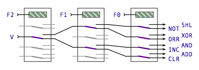
This design is taken directly from the Harry Porter Relay Computer and as usual I’ll need to adapt it to use the smaller DPDT relays. The physical layout diagram is therefore:
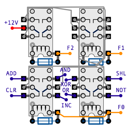
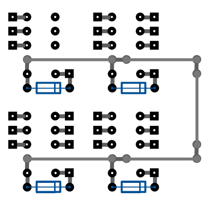
… and here’s the same diagram with relays and wires omitted and with partial ground rails added …
In the next couple of posts I’ll cover the Zero Detect circuit and Condition Registers and then cover putting all three together on the ALU Control Card.