In this post I’ll wrap up this ‘mini-series’ of trying to explain away the various bits of the architecture that will make up my relay computer project — finally now we come on to Programming and Control of the computer. Here again, for the last time, is the architecture I’ll be building against (from the Harry Porter Relay Computer)
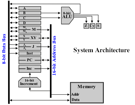
With all the various parts of the architecture I’ve discussed so far — the busses, registers, memory and ALU — we have a computer that could be manually operated, albeit laboriously, to perform various tasks. Actually, in fact, this will be the first milestone in the construction of my computer … that I can manually operate what I have built so far just as the computer will itself when it is able to execute programs. Just to give you a feel for exactly how labour intensive even a simple task would be here are the manual steps to subtract 6 from 10:
- Enter the value 10 (in binary as 00001010) on to the data bus (there will be physical toggle switches to allow the user to do this).
- Turn the load switch on then back off again on the C register. This will store the value 10 on this register.
- Enter the value 6 (in binary as 00000110) on to the data bus.
- Turn the load switch on then back off again on the B register. This will store the value 6 on this register.
- We are now in our starting state for performing the subtraction. However, the ALU doesn’t have a subtract function so we’re going to have to do a little more work ourselves.
- Set the ALU to the NOT function. Load register A (toggle the load switch on then off). Turn off the ALU.
- Select register A (turn on the select switch so that its value is placed on the data bus) and load register B then turn off the select switch on register A. The value NOT-6 is now copied in to register B (replacing the original 6 value).
- Set the ALU to the Increment function, load register A then turn off the ALU. We now have the value (NOT-6)+1 … the two’s complement of 6 which represents -6 in binary.
- Again, select register A, load register B then unselect register A. We now have -6 in register B and 10 still in register C. Finally now we can add the numbers together.
- Set the ALU to the Add function, load register A then turn off the ALU. We now have the value 4 in register A (-6 + 10) as expected.
Phew, all that just to subtract two numbers and we didn’t even include taking the starting values from somewhere in memory and then putting the result back in memory afterwards. Now of course, in a modern computer the ALU will likely have a subtract function built in so the above operation is much simpler (but at the expense of the ALU being more complex) but even in a computer that does perform all the above operations all of this happens in the blink of an eye. Well, that is, a blink of an eye for a modern wholly electronic computer but what I’m building here is a relay computer which is electromechanical so it’s not the fastest thing in the world and so the above would take a fair bit of time to complete (depending ultimately on how fast the relays can reliably switch before we get data corruption creeping in).
You can probably see now that although operating a computer manually to perform a task is certainly possible it’s not all that much fun (well, at least not after the first couple of times of doing it). What’s really needed is the ability to give the computer a set of instructions/steps to follow that it can work through in its own time and then get back to us when it’s finished with the result. This is where the computer program comes in … it’s a set of sequential steps telling the computer what action to perform. Sequential steps alone would be enough to perform our subtraction routine above but where the real power comes is when the program can take differing actions based on a result the computer is generating so for example we could subtract the two numbers and then skip to a different part of the program depending on whether the result was positive or negative (or zero, or caused a carry — all driven by the ALU condition registers).
If we look at the subtraction steps above we can break them down in to the following operations (after placing the values 10 and 6 in the registers):
- ALU:NOT, Load A
- Select A, Load B, Unselect A
- ALU:Increment, Load A
- Select A, Load B, Unselect A
- ALU:Add, Load A
If you imagine that each part of the computer that can be manipulated has switches to control each operation (so load/set registers, operate the ALU, load/store in memory, etc … basically a big pile of switches). These steps are the switches that need to be toggled for each step. You can maybe see a pattern developing here … some of the steps are very similar. If we make things more concise again:
- ALU:NOT to A
- Copy A to B
- ALU:Increment to A
- Copy A to B
- ALU:Add to A
There’s actually two classes of step here: one is to perform an ALU operation (placing the value in A) and the other is to copy a value (from A to B). Equally we could perform any of the ALU operations using the same ‘class’ of step (and place the value in a different register [but not B or C]) and we could move a value from any register to any register. So, if we give the computer an instruction/step of a certain ‘class’ it will then know which switches to toggle and in which order which means we can get on with the job of just telling it, at a higher level, which steps to perform without worrying about what the computer will actually have to do to complete that step. Equally, the computer can just concern itself with performing the step exactly as requested without worrying about the overall task. We now need somewhere to store the current step so that the computer can work out which switches to throw and that’s where the instruction register comes in — we simply place an 8-bit value in here and that then tells the computer what step to perform. Simply place?! Well, we need someway of encoding all the possible task ‘classes’ that the computer can perform along with extra details (the copy command needs to know which register to copy from and to for example) in to a single 8-bit value that the computer can then decode. This encoded value is called an opcode (operation code) and the copy instruction (or move as it’s commonly known) and the ALU instruction work like this:
- Move/Copy (MOV) : 00sssddd
- sss = source register (000:A, 001:B, 010:C, 011:D, 100:M1, 101:M2, 110:X, 111:Y)
- ddd = destination register (000:A, 001:B, 010:C, 011:D, 100:M1, 101:M2, 110:X, 111:Y)
- ALU (ALU) : 1000dfff
- d = destination register (0:A, 1:D)
- fff = function (000:not used, 001:ADD, 010:INC, 011:AND, 100:OR, 101:XOR, 110:NOT, 111:SHL)
So, for example: 00000001 is the opcode for MOV A to B; 10000110 is the opcode for ALU NOT to A. You can see here now that although in theory you could store the ALU result in any register other than B or C there’s only room in the opcode for a single bit … that’s why we restrict ourselves to only allowing A or D as a destination for ALU operations. There are several more opcode classes and I’ll put a post up a bit later which lists the full set. Hopefully now though you can now see that by using the opcodes we can give the computer the following instructions to perform the same subtraction program:
10000110    (ALU:NOT to A)
00000001    (MOV A to B)
10000010    (ALU:INC to A)
00000001    (MOV A to B)
10000001    (ALU:Add to A)
As a quick aside you can probably see that programming the computer is quite intense for the person writing the program (the programer). To make things easier we can use mnemonics to make the opcodes easier to remember and work with — one particular set of these mnemonics is called assembly language and would look a bit like the following:
not a
mov b, a
inc a
mov b, a
add a
Much easier to remember :) Note that each mnemonic has a matching opcode so effectively before we can enter the program into the computer we need to convert the mnemonics back into to opcodes. Incidentally, the sharp eyed out there might have noticed that the move command is ‘mov b, a’ rather than ‘mov a, b’ as you might otherwise expect … it does actually mean copy value a in to b but convention dictates the move command has the destination followed by the source in assembly language.
Wow, this post is getting quite big and we’re not quite there yet — we need to cover how we actually execute the program now we’ve created it. Let me give you, and I, a breather and I’ll continue in the next post.