In this post I’ll continue to try and explain away the various bits of the architecture that will make up my relay computer project — this time it’s buses and registers. Here again is the architecture I’ll be building against (from the Harry Porter Relay Computer):
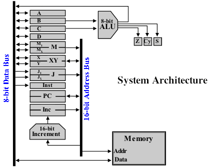
Buses are simply a set of wires that connect up the various parts of a computer. As each wire can carry 1 bit it therefore takes 8 wires to carry 8 bits. In this architecture the data bus is 8 bits wide and the address bus (which I’ll go in to further in the next post on the memory) is 16 bits wide. You can only have a single value on a bus at the same time so any part of the computer that needs to talk to another part has to wait its turn for the bus to become free. It’s worth noting though that because the data and address bus are physically separate you can have different values on each without problem. In the diagram above the data bus is shown as a thick line on the left and the address bus is the thick line on the right. In real life, of course, there would be as many wires as there are bits but to simplify the diagram they’re shown as a single thick line.
Registers hold a binary value for use when performing calculations and moving data around. They are typically very fast (compared to storing things in memory) but there’s a fixed number of them. Most registers are available for general use and can be read from as well as written to but some special purpose registers are read only or write only. Looking at the system architecture diagram above the registers are shown as rectangles down the middle of the diagram. In this architecture there are eight ‘general purpose’ registers (A, B, C, D, M1, M2, X and Y) which can hold 8 bits each and can be set from or loaded onto the data bus (shown by the double headed arrow to the data bus). Four of the ‘general purpose’ registers (M1, M2, X and Y) combine together in pairs to act as a single 16-bit register (M and XY). The XY register can be set from or loaded onto the address bus while the M register can only be loaded onto the address bus (not set from it). Although these are all ‘general purpose’ registers and can be used for any purpose by the computer programmer some have a special meaning in certain situations: B and C feed the Arithmetic Logic Unit (ALU - I’ll cover this in a later post); M1 and M2 are typically used to set the current memory address via M (again, I’ll talk about memory later).
In addition to the ‘general purpose’ registers there are some additional registers that serve a specific purpose. J1 and J2 are 8-bit registers that can only be set from the data bus — these join together to form the 16-bit J register which can be loaded onto the address bus. J is typically used to store an address in memory that we may wish to jump to if needed. For example, a programmer might say subtract number B from A and if the result is zero go to line 50 in the code otherwise carry on to the next line of code — in this case we’d store the address of line 50 in the J register ready for the jump if we need it. Finally there is an 8-bit Instruction register (Inst) and a 16-bit Program Counter (PC) register — I’ll go into what these are for later on but for now you can see from the architecture diagram that the Inst register can only be set from the data bus and the PC register can be set or loaded from/onto the address bus.
There is actually another three registers ‘hiding’ in the top right of the diagram — registers Z, Cy and S. These are special 1-bit registers which are set by the ALU. I’ll cover these — yup, you guessed it — in a later post all about the ALU.
So, upcoming posts on my ’todo’ list are: Memory, the ALU and Programming/Control. Those of you who have been reading since my first post will know that I’m playing catch up with my blog — in real life I’m already soldering things together (and watching the delivery lead time on my relays I ordered dissapointingly slip further and further back). I’m taking lots of pictures as I’m putting things together so I’ve got plenty to put on here when I’m finally up to date.