This post covers the design of the Zero Detect circuit which along with the 3-to-8 Function Decoder (covered in my last post) and the Condition Registers (next post) make up the ALU Control Card. The Zero Detect circuit … wait for it … detects when a value is zero. The value in question is taken from the data bus so in effect we’re detecting when no bits are set. The output from this circuit is then passed to the Condition Registers so that the current value can be stored for future operations. The circuit itself is nice and simple:
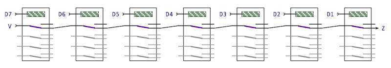
If all inputs are off then the output Z is on otherwise, if any input is on, then Z is off. This design is taken from the Harry Porter Relay Computer as usual but this is one of the rarer cases where my translating the design to use DPDT relays doesn’t increase the physical relay count:
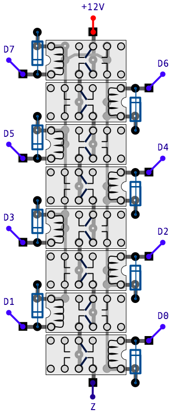
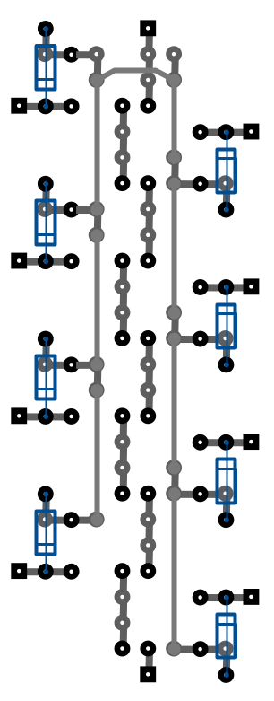
To save space and wire links this design places the relays in alternating orientations so that the switches line up as required and all the inter-relay connections are made on the solder side of the board. With the relays and inputs/outputs hidden it looks like this:
… and that’s it for the Zero Detect circuit. In the next post I’ll cover the Condition Registers and then following that I’ll move on to putting the ALU Control Card together.