This post covers the design of the ALU Condition Registers which along with the 3-to-8 Function Decoder and Zero Detect circuit (both covered in my previous posts) make up the ALU Control Card. There are three Condition Registers in this computer:
- Carry: set when a bit is carried in the Arithmetic Unit (which can also indicate arithmetic overflow depending on the interpretation of the numbers being added).
- Zero: set when the ALU result is zero (all bits are off).
- Sign: set when the most significant bit is set (which would indicate a negative result for signed values). This condition has no direct meaning for unsigned numbers (other than indicating the number has a value of 128 or more).
When the ALU performs an operation the current values of these three conditions are stored in the condition registers so that they can be referred to in other operations. An example of this would be where given two numbers the first is negated and then added to the second … if the two numbers are equal it will result in zero and therefore the Zero condition will be set. Based on this condition register being set you could then branch to a different location in the executing program if desired. That is, for example, if number A and B are equal then go to line C in the program. It’s this ‘branching’ functionality that elevates the computer in terms of power and flexibility and the condition registers are at the heart of this.
In the most basic terms we can store a single bit in a relay as follows:
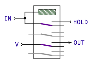
In its initial state the register is off and both the IN and HOLD inputs are off. A value is applied to the IN output and then the HOLD input is set on and the value at IN removed. If the value was set then the relay would be activated allowing the HOLD input to keep the relay on. The relay will then remain on until the HOLD input is set off. Separately to this power is supplied directly to one of the other relay switches and provides an isolated source of the value held in the relay.
This basic design does need some ‘support’ to gate the input to the relay to ensure that it is only fed to the relay when needed and that the hold line is off when ’loading’ the relay (this also ensures that the hold line can’t back-feed the input line accidentally). Adding these control and gating relays gives us the following:
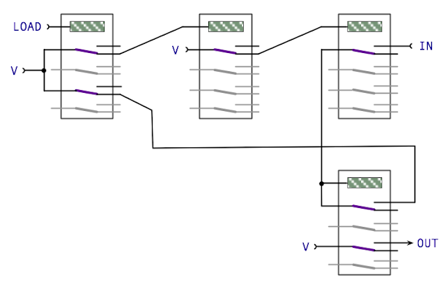
This may look a little over complicated at first but is designed to avoid feedback and oscillation in the control lines (where the relay would turn on and off rapidly turning it into a buzzer … and eventually burning it out). The design for this register is, again, taken from the Harry Porter Relay Computer (there’s also a nice explanation on the issue of feedback and oscillation here in the evolution of this design). Using this base design I can now modify it to use my DPDT relays and add the other two condition registers required:
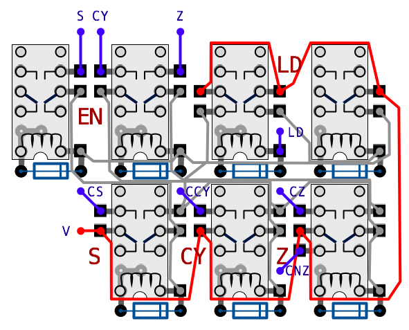
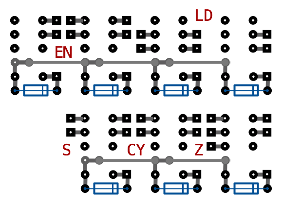
It’s quite a ‘busy’ layout but breaking it down: the two relays at the top right are the Load circuit supplying the input gate enable and register hold lines; the two relays at the top left are the input gating circuit and finally the bottom three relays are the registers themselves. The there inputs are S, CY and Z … each has its respective condition register output CS, CCY and CZ. There is also an additional CNZ which is Not-Zero (the inverse of Zero) which is useful for simplifying the control circuitry that is driven by these outputs. Likewise, if we needed, we could produce CNS and CNCY (not Sign and not Carry) in a similar fashion. With the relays, inputs/outputs and wire links hidden and partial ground rails added the design looks like this:
With the design for the Condition Registers now complete we have everything needed to put the ALU Control Card together and that’ll be covered in the next post.